Flexible coupling

A flexible coupling and shaft hole technology, which is applied in the field of measuring while drilling, can solve the problems that the geometric shape does not meet the requirements and the power requirements, and achieves the effects of continuous and reliable power transmission, simple structure and high efficiency

Active Publication Date: 2016-03-02
BC P INC CHINA NAT PETROLEUM CORP +1
View PDF9 Cites 3 Cited by
  • Summary
  • Abstract
  • Description
  • Claims
  • Application Information

AI Technical Summary

Problems solved by technology

[0005] However, the flexible coupling represented by the above-mentioned patent documents cannot meet the power requirements for transmitting the rotating moti...

Method used


Image

  • Flexible coupling
  • Flexible coupling
  • Flexible coupling

Examples


Embodiment 1

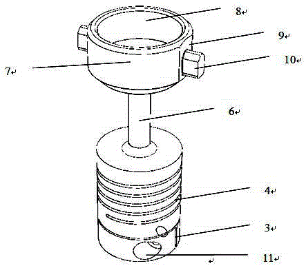
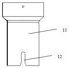
[0029] As a preferred embodiment of the present invention, the present invention discloses a flexible coupling, which includes a part body composed of a rotating body. The part body includes a main body upper part 7, a main body middle part 6 and a main body lower part, and the main body lower part is integrally It is cylindrical, and there is a shaft hole 1 for connecting with the motor output shaft 14 along the axial direction of the lower part of the main body, and a helical cutting groove 4 is opened in the lower part of the main body; The diameters of 7 are greater than the diameter of the middle part 6 of the main body; the upper part 7 of the main body is cup-shaped as a whole, and the side of the upper part 7 of the main body protrudes and is provided with an ear structure 10 coupled with the notch 12 on the coupling part 11, and the top surface of the upper part 7 of the main body A concave hole 8 is provided.

Embodiment 2

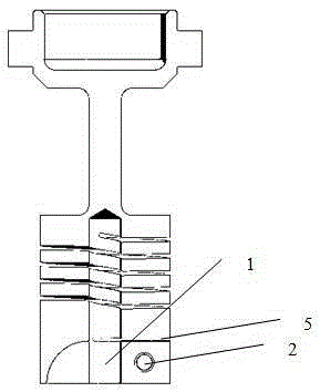
[0031] As the best implementation mode of the present invention, on the basis of embodiment 1, refer to the attached figure 1 with 2 , in the radial direction, the depth of the helical cutting groove 4 extends from the surface of the lower part of the cylindrical main body to the shaft hole 1 in the lower part of the main body, and in the axial direction, the helical cutting grooves 4 are arranged in layers. A horizontal cutting groove 5 is provided at the lower part of the spiral cutting groove 4 . The lower part of the main body is provided with a side slit 3, and the outside of the side slit 3 is provided with a threaded hole 2. Two parallel facet structures 9 are arranged on the side of the upper part 7 of the main body, and two ear structures 10 are symmetrically arranged on the facet structures 9 . The main body upper part 7, the main body middle part 6 and the main body lower part are integral molding structures.

[0032] After the motor output shaft 14 is installed ...


PUM


Abstract

The invention discloses a flexible coupling which comprises a part main body composed of a revolved body, wherein the part main body comprises a main body upper part, a main body middle part and a main body lower part; the integral main body lower part is cylindrical; a shaft hole used for connecting a motor output shaft is formed in the axial direction of the main body lower part; a spiral cutting groove is formed in the main body lower part; the main body middle part adopts a spindly cylindrical shape; the diameters of the main body lower part and the main body upper part are larger than the diameter of the main body middle part; the integral main body upper part adopts a cup shape; ear structures coupled with grooves in coupling parts are arranged on the side surface of the main body upper part in a stretching manner; and an inward concave hole is formed in the top surface of the main body upper part. According to the flexible coupling, firstly, the requirement for transferring power of the rotating action of a motor in a measurement-while-drilling instrument mud-pulse generator during directional drilling can be met, geometric structures of the flexible coupling are particularly applicable to the connection of the motor output shaft and the coupling parts, and the functional requirement of flexible connection can be met.

Description

technical field [0001] The invention relates to the technical field of measuring-while-drilling instruments, in particular to a flexible coupling used in a mud pulse generator of a measuring-while-drilling instrument for petroleum directional drilling for transmitting the rotational motion of a motor. Background technique [0002] In oil, natural gas or geothermal drilling, measurement-while-drilling instruments can participate in MWD (Measurement-While-Drilling) or LWD (Logging-While-Drilling) to measure drilling engineering parameters during drilling, such as borehole trajectory and deviation , azimuth, tool face, or various formation parameters, such as formation resistivity, natural gamma ray, formation porosity, etc., the measurement-while-drilling instrument is for real-time conversion of these engineering parameters and geological parameters corresponding to formation depth in the drilling process from The instruments used for underground transmission to the surface, ...

Claims


Application Information

Patent Timeline
IPC IPC(8): F16D3/26F16D3/38
CPCF16D3/26F16D3/387
Inventor 张铎谭清明黄攀福刘伟白璟禹荣彭文朱效忠肖占朋张继川黄崇君连太炜雍鹏廖冲
Owner BC P INC CHINA NAT PETROLEUM CORP
Why Eureka
Try Eureka