
Starting circuit for direct-current switch power supply

A technology of power start and DC switching, applied in electrical components, output power conversion devices, etc., can solve the problems of inability to start, large static power consumption, etc., and achieve the advantages of less working components, simple design, low cost, and avoiding high static loss. Effect

Inactive Publication Date: 2009-12-16
HOHAI UNIV
View PDF0 Cites 10 Cited by
  • Summary
  • Abstract
  • Description
  • Claims
  • Application Information

AI Technical Summary

Problems solved by technology

Aiming at the shortcomings of the wide-range, low-input-voltage power-starting circuit that cannot be started under low-input voltage and high static power consumption under high-input voltage, the present invention proposes a power-starting circuit that can work under low-input voltage conditions

Method used


Image

  • Starting circuit for direct-current switch power supply
  • Starting circuit for direct-current switch power supply
  • Starting circuit for direct-current switch power supply

Examples


Embodiment Construction

[0021] The technical scheme of the present invention is further specifically described below in conjunction with the accompanying drawings:

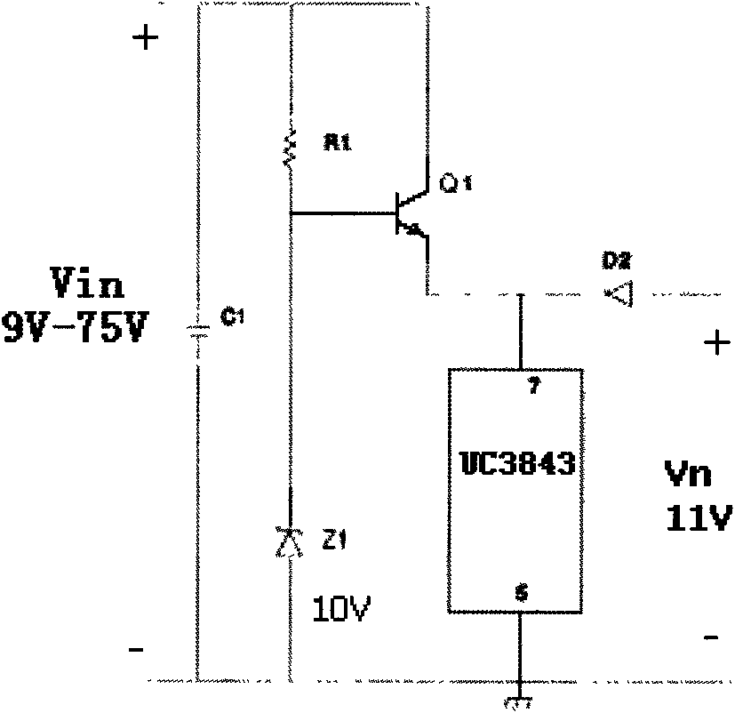
[0022] figure 1 It is a schematic diagram of a typical starting circuit, and its starting circuit is composed of R1, Z1, and Q1. When the circuit is energized, the base voltage of Q1 is set to 10V by the Zener tube Z1. Since the PN junction voltage drop of the Q1 tube is 0.7V, a voltage of 9.3V is generated at the emitter of Q1 to supply power to the chip UC3843. When the power supply is working normally, the auxiliary winding provides the chip with an operating voltage of 11V, and the Q1 tube is turned off under the back pressure. There are two significant disadvantages in the traditional start-up circuit: (1) Since the working principle of the Zener tube needs to provide a certain quiescent operating current to the Zener tube Z1, the maximum resistance value that the current-limiting resistor R1 can usually take is determined by the l...


PUM


Abstract

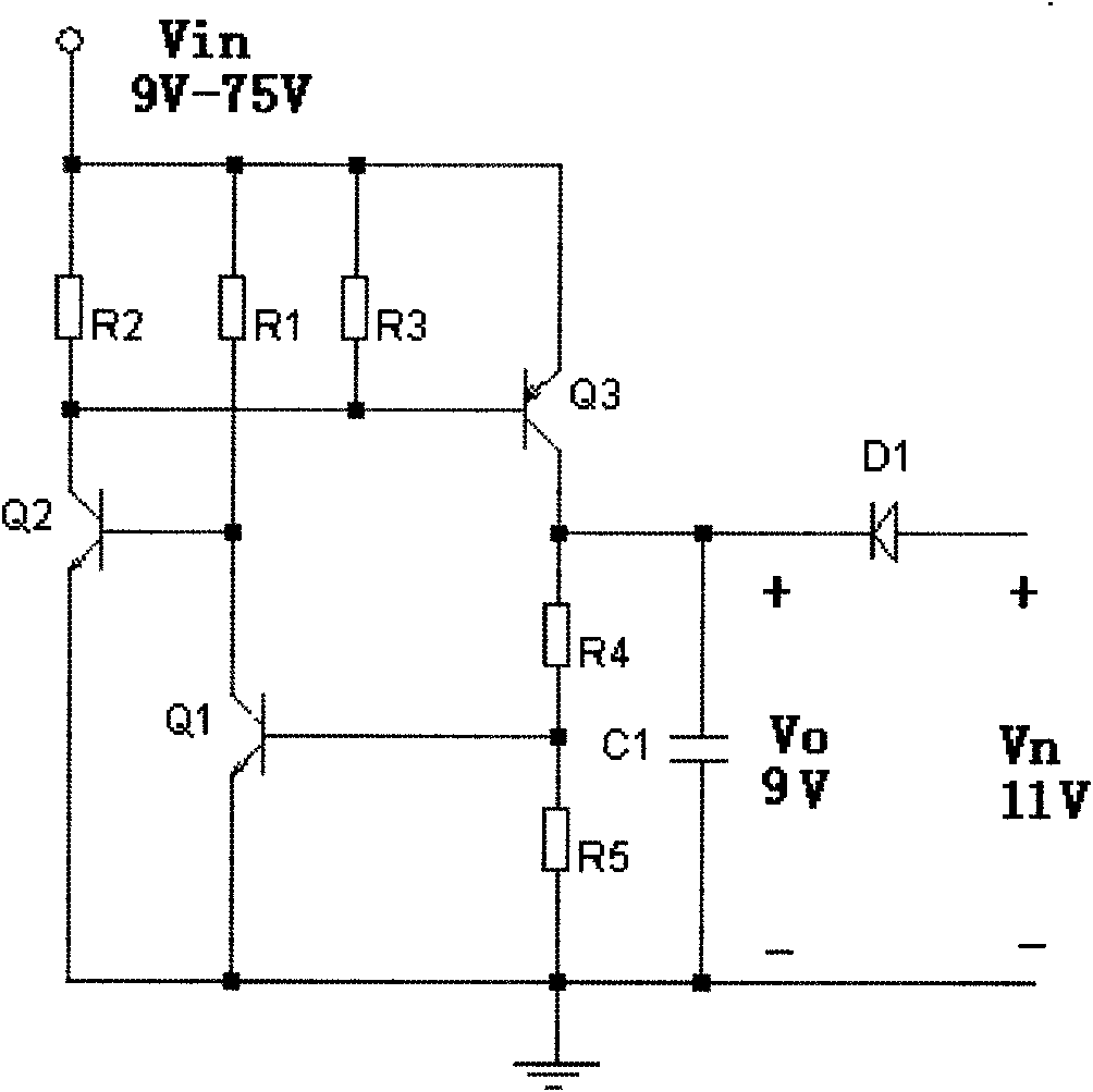
The invention provides a starting circuit for a direct-current switch power supply, which comprises a first resistor R1, a second resistor R2, a third resistor R3, a fourth resistor R4, a fifth resistor R5, a PNP triode Q3, a first NPN triode Q1, a second NPN triode Q2 and a diode D1. The starting circuit for the direct-current switch power supply not only meets the requirement that a switch power supply module supplies the start working voltage to the power supply under the condition of low input voltage, but also overcomes the defect that the conventional starting circuit has large static power consumption under the condition of high input voltage. The starting circuit has the advantages of simple circuit structure, small volume, reliable performance and the like, and has practical application value for the switch power supply working under the condition of wide input working voltage and low voltage start.

Description

technical field [0001] The invention relates to a starting circuit of a DC switching power supply, in particular to the technical field of a starting circuit of a DC / DC direct current power supply module suitable for wide input range and low-voltage starting. Background technique [0002] In many special application environments, it is often encountered that the input voltage for powering electronic equipment varies in a wide range. In order to ensure that the equipment has a reliable power output under ultra-wide range and low-voltage power supply conditions, it is necessary to first solve the design problem of the power supply starting circuit under various input voltage conditions. [0003] At present, the typical operating voltage value of the low-voltage power supply control chip announced at home and abroad is 8.5V. Due to the PN junction voltage drop (usually 0.7V) in the PNP tube in the traditional power supply start-up circuit, when the power supply works under low ...

Claims


Application Information

Patent Timeline
Patent Type & Authority Applications(China)
IPC IPC(8): H02M1/36
Inventor 周岩王柏林
Owner HOHAI UNIV
Learn More