Single-phase electronic type electric energy meter electric source

An electric energy meter, electronic technology, applied to electrical components, adjusting electric variables, instruments, etc., can solve the problems of electricity cost loss, reliability reduction, inconvenient promotion, etc., and achieve low cost, high reliability, and free setting of power supply voltage certain effect

Inactive Publication Date: 2009-10-21
SHENZHEN STAR INSTR
View PDF1 Cites 9 Cited by
  • Summary
  • Abstract
  • Description
  • Claims
  • Application Information

AI Technical Summary

Problems solved by technology

Because this kind of circuit does not use switching power supply, its work is relatively reliable, so this kind of circuit or similar circuits are widely used in single-phase electronic energy meters. However, this kind of circuit has high requirements on the power grid. The single-phase electronic energy meter of this circuit often fails to work, resulting in the loss of electricity bills
In order to overcome the above problems, one of the schemes is to adopt a switching power supply scheme, such as the patent number disclosed in the Chinese utility model patent: 02271250.X and the technical scheme named "switching power supply with a wide input voltage range". The circuit structure is mainly composed of a control chip, a transformer, an electronic switch, a start-up circuit of the control chip, a voltage feedback circ

Method used


Image

  • Single-phase electronic type electric energy meter electric source
  • Single-phase electronic type electric energy meter electric source
  • Single-phase electronic type electric energy meter electric source

Examples


specific Embodiment approach

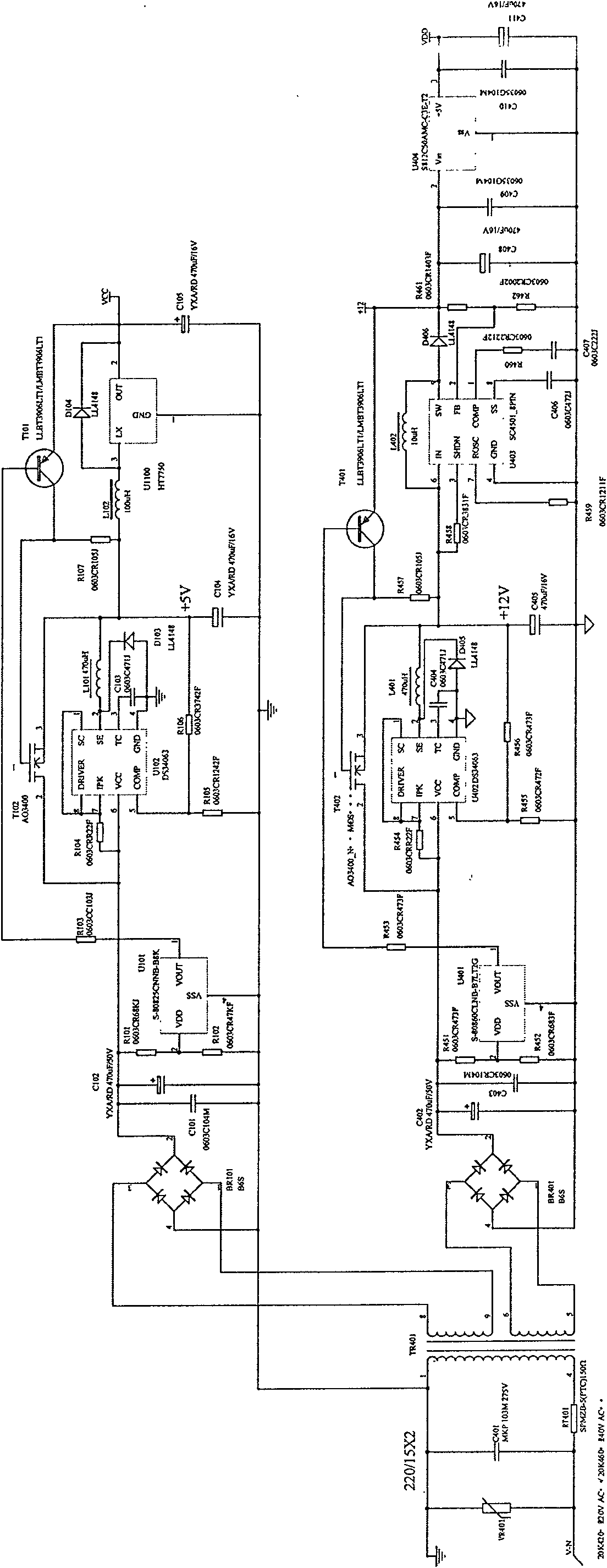
[0013] detailed description: image 3 A detailed circuit diagram of the circuit. The power supply implements two isolated power supplies, 5V and 12V, 5V is used to supply power to the metering chip, and 12V is used to supply power to the CPU. The 5V power supply: the primary winding of the power frequency transformer TR401 is connected to the external power grid, the input terminal of the rectifier bridge BR101 is connected to a set of secondary windings of the power frequency transformer TR401, and the output terminal of the rectifier bridge BR101 is filtered by two capacitors C101 and C102 connected in parallel , the integrated circuit block of the sampling control circuit adopts S-80825, the switch circuit SW1 is composed of a resistor R103, a transistor T101, a clamping resistor R107 and a switch tube T102, and the switch tube T102 uses an N-channel MOS tube A03400, and one end of the resistor R103 is connected to the sampling The output end of the control circuit, the ot...


PUM


Abstract

The invention relates to a single-phase electronic type electric energy meter electric source which comprises an industrial frequency transformer T1, a rectification circuit D1, a filter circuit C1, a sampling control circuit, a switch circuit SW1, a voltage reduction DC/DC circuit and a voltage booster DC/DC circuit, wherein industrial frequency AC Vin reduces voltage through the industrial frequency transformer T1 and then obtains an DC voltage end V1 through the rectification circuit D1 and the filter circuit C1; the V1 end is directly connected with an input end of the voltage reduction DC/DC circuit; the voltage reduction DC/DC circuit outputs DC V2 to the voltage booster DC/DC circuit; an output end V3 of the voltage booster DC/DC circuit supplies a stable working electric source for a CPU and a metering chip of an electric energy meter; one end of the sampling control circuit is connected with the V1, and the other end is connected with a control end of the switch circuit SW1; and the input end and the output end of the switch circuit SW1 are respectively connected with the input end and the output end of the voltage reduction DC/DC circuit. The working performance of the electric source with the structure is stable, the production cost is low, and the working scope of an electric source meter can reach AC40 to 400V.

Description

technical field [0001] The invention belongs to the field of electronic measuring instrument manufacturing, and in particular relates to a single-phase electronic electric energy meter power supply. Background technique [0002] The power supply circuit of the existing single-phase electronic energy meter mostly adopts a power frequency transformer plus a linear voltage stabilizing circuit (such as figure 1 shown), the working range is between 85V-280. Because this kind of circuit does not use switching power supply, its work is relatively reliable, so this kind of circuit or similar circuits are widely used in single-phase electronic energy meters. However, this kind of circuit has high requirements on the power grid. The single-phase electronic energy meter of this circuit often fails to work, resulting in the loss of electricity bills. In order to overcome the above problems, one of the schemes is to adopt a switching power supply scheme, such as the patent number discl...

Claims


Application Information

Patent Timeline
IPC IPC(8): H02M7/04H02M3/155
Inventor 嵇成友龙代文
Owner SHENZHEN STAR INSTR
Why Eureka
Try Eureka