Static and dynamic composite sealing structure and method for rotary machine rotor

A composite sealing and rotating machinery technology, which is applied in the direction of engine sealing, mechanical equipment, engine components, etc., can solve the problems of limited use and poor economical use, reduce temperature rise, avoid short circuit or corrosion, and improve sealing effect Effect

Active Publication Date: 2016-03-02
NORTHWESTERN POLYTECHNICAL UNIV
View PDF7 Cites 7 Cited by
  • Summary
  • Abstract
  • Description
  • Claims
  • Application Information

AI Technical Summary

Problems solved by technology

When the rotor speed is high, the use of contact seals will be limited due to relatively large friction and wear
Simple pneumatic seals cannot meet the requirements of high load, high speed and high precision of the bearing rotor system, and the economical efficiency of use is not good.

Method used


Image

  • Static and dynamic composite sealing structure and method for rotary machine rotor
  • Static and dynamic composite sealing structure and method for rotary machine rotor
  • Static and dynamic composite sealing structure and method for rotary machine rotor

Examples


Embodiment Construction

[0021] Now in conjunction with embodiment, accompanying drawing, the present invention will be further described:

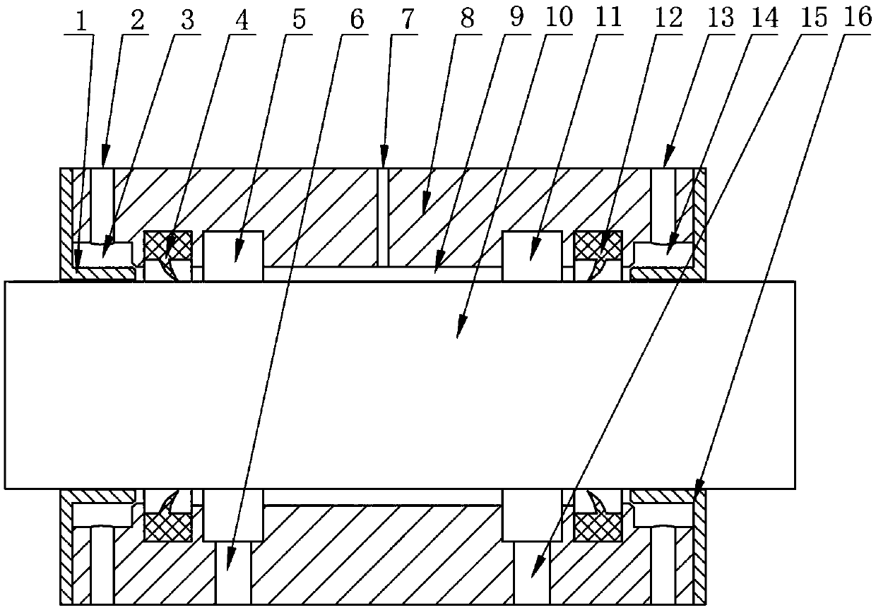
[0022] Such as figure 1 As shown, the two ends of the sliding bearing are provided with a left annular oil return groove 5 and a right annular oil return groove 11, and a left lip seal ring 4 and a right lip seal ring are arranged on the outer sides of the left annular oil return groove 5 and the right annular oil return groove 11 respectively. 12. On the outside of the left lip seal ring 4 and the right lip seal ring 12, there are left slit annular air pressure chamber 3, right slit annular air pressure chamber 14, left slit annular air pressure chamber 3, and right slit annular air pressure chamber 14 is connected with the external high-pressure air source by air inlet. Before the rotor is started, the left lip seal ring 4 and the right lip seal ring 12 are tightly attached to the rotor to prevent the lubricating fluid flowing out from the bearing gap from flo...


PUM


Abstract

The invention relates to a static and dynamic composite sealing structure and method for a rotary machine rotor. High-pressure lubricating liquid is added to a sliding bearing, so that in the floating stage and the low-speed rotating stage of the rotor, leakage of the lubricating liquid is stopped through the static sealing function of lip sealing rings with lip points attached to the rotor. Along with increase of the rotating speed of the rotor, an air inlet channel of an external high-pressure air source is opened, air pressure is slowly increased, the lip points of the lip sealing rings are separated from the surface of the rotor, and an annular air wall is formed on the surface of the rotor; and a large part of lubricating liquid is thrown into a left annular oil return groove and a right annular oil return groove to flow out due to the centrifugal function, and a small part of lubricating liquid flowing in the axial direction of the rotor is limited from flowing through sealing of the floating lip points and dynamic sealing of the air wall. Thus, good sealing is guaranteed within the start, stop and rotating full-speed range of the rotor.

Description

technical field [0001] The invention belongs to the field of sealing, and in particular relates to a static and dynamic composite sealing structure and method for a rotary machine rotor. Background technique [0002] Seals are generally divided into two types: static seals and dynamic seals, and each seal type has a variety of sealing methods. Static seals, such as O-ring seals, are often used between the two static surfaces of the rotor. This type of seal is safe, reliable, simple and economical, and has low structural requirements. However, for the sealing of the moving surface, especially under high-speed conditions, the static seal is easy to wear, and the service life is greatly reduced, which cannot meet the requirements of use. Dynamic seals include labyrinth seals, centrifugal seals, spiral seals, magnetic seals, air pressure seals, etc., and the usage occasions of each sealing method are different. Labyrinth seals, air pressure seals and centrifugal seals are rela...

Claims


Application Information

Patent Timeline
Patent Type & Authority Applications(China)
IPC IPC(8): F16J15/16F16J15/40
Inventor 王琳张瑜
Owner NORTHWESTERN POLYTECHNICAL UNIV
Why Eureka
Try Eureka