
Reactor melt retention apparatus

A technology in a melt and a device, which is applied in the field of the reactor melt retention device, and can solve the problems of threatening the integrity of the containment and the large-scale release of fission products.

Inactive Publication Date: 2016-03-02
STATE NUCLEAR POWER TECH +1
View PDF8 Cites 10 Cited by
  • Summary
  • Abstract
  • Description
  • Claims
  • Application Information

AI Technical Summary

Problems solved by technology

However, as the power of the reactor increases, the failure probability of the pressure vessel increases. Once the melt leaks, there will be reactions outside the reactor, such as the reaction between the melt and the coolant, the reaction between the melt and concrete, and the hydrogen explosion. These phenomena will seriously threaten the containment. The integrity of the fission products will eventually lead to a large-scale release of fission products, which will have a huge impact on the environment

Method used


Image

  • Reactor melt retention apparatus
  • Reactor melt retention apparatus
  • Reactor melt retention apparatus

Examples


Embodiment Construction

[0021] The present invention will be described in detail below in conjunction with specific embodiments. Wherein, the same reference numerals are used to denote the same or similar components. These examples are illustrative only, and the present invention is by no means intended to be limited to these illustrative examples only.

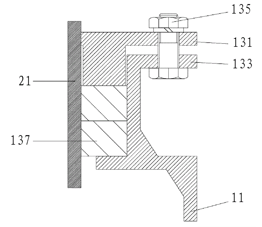
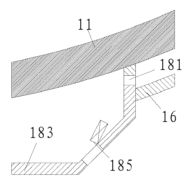
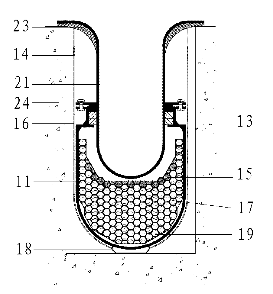
[0022] figure 1 A front cross-sectional view of a smelt retention device according to an embodiment of the invention is shown. The smelt retention device includes a trap housing 11 , a trap seal 13 , a sacrificial material 19 , a water inlet device 18 , and an insulation layer 16 . Sacrificial material 19 is disposed within trap housing 11 . The smelt retention device is entirely disposed in the space surrounded by the shielding wall 24 . The trap seal 13 is sealingly connected to the outer wall of the pressure vessel 21 . The insulation layer 16 is connected to the pressure vessel support 23 .

[0023] like figure 1 As mentioned above, the c...


PUM


Abstract

The invention relates to a reactor melt retention apparatus. The apparatus comprises a catcher shell, a catcher sealing device, a buffer area, a sacrificial material area, a heat insulation layer and a water inlet device. A sacrificial material is used to dilute a melt in order to reduce the heat flow density, and passively cooled melt retention in a channel between the catcher shell and the heat insulation layer is used to realize melt retention under severe accidents in order to alleviate severe accidents, avoid large-scale release of radioactive fission products and reinforce the safety performances of reactors, so the large-scale passive pressurized water reactor severe accident alleviation capability is enhanced.

Description

technical field [0001] The present application relates to a reactor melt retention device, and more particularly, to a wet reactor passive melt retention device. Background technique [0002] The descriptions in this section merely provide background information related to the present application and in no way should be construed as admissions of any prior art. [0003] With the advancement of the research and development of the third generation of high-power reactors in China, the AP and CAP series of high-power reactors that my country mainly promotes have many controversies in terms of severe accident mitigation technologies, especially more questions have been raised about in-reactor retention and out-of-reactor retention. [0004] At present, AP or CAP series reactors adopt IVR (In-Vessel Retention) technology as a severe accident mitigation measure. For AP or CAP series reactors, when the core cannot be effectively cooled under an accident, after the core reaches a ce...

Claims


Application Information

Patent Timeline
IPC IPC(8): G21C9/016
CPCY02E30/30
Inventor 马莉李晶汲水
Owner STATE NUCLEAR POWER TECH
Learn More