Method and system for setting voltage change rate criterion of direct current line travelling wave protection

A technology of voltage change rate and DC transmission system, applied in the direction of emergency protection circuit devices, electrical components, etc., which can solve problems such as incorrect operation of DC lines, low accuracy rate, and uncertain change boundaries of protection characteristic quantities

Active Publication Date: 2016-03-02
ELECTRIC POWER RESEARCH INSTITUTE, CHINA SOUTHERN POWER GRID CO LTD
View PDF2 Cites 13 Cited by
  • Summary
  • Abstract
  • Description
  • Claims
  • Application Information

AI Technical Summary

Problems solved by technology

[0011] Fault traveling waves contain a wealth of transient information. At present, the sampling interval of traveling wave protection devices is generally 100 μs or 150 μs. Due to the randomness of the sampling of protection devices, the actual sampling data must have fault information loss compared with the original data. Therefore, it is impossible to determine the change boundary of the protection characteristic quantity when there is an internal fault and an external fault.
It is precisely because the change boundary of the protection characteristic quantity cannot be determined, the current criterion setting of the voltage change rate of the traveling wave protection can only rely on the method of trial and error.
The method of trial and error is difficult to exhaust all possibilities. Once an unexpected situation occurs in actual operation, it is very likely to cause incorrect action of the DC line traveling wave protection
[0012] Therefore, the accuracy of the existing method for determining the voltage change rate criterion of traveling wave protection for DC transmission lines is not high

Method used


Image

  • Method and system for setting voltage change rate criterion of direct current line travelling wave protection
  • Method and system for setting voltage change rate criterion of direct current line travelling wave protection
  • Method and system for setting voltage change rate criterion of direct current line travelling wave protection

Examples


Embodiment Construction

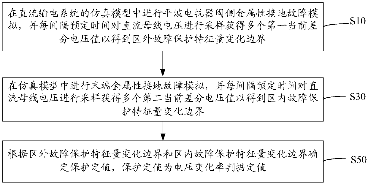
[0059] Such as figure 1 As shown, a method for setting the voltage change rate criterion of DC line traveling wave protection includes the following steps:

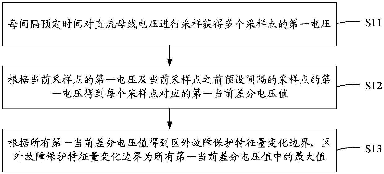
[0060] S10: In the simulation model of the DC transmission system, simulate the metallic ground fault on the valve side of the smoothing reactor, and sample the DC bus voltage at predetermined intervals to obtain a plurality of first current differential voltage values ​​to obtain the external fault protection feature volume change boundaries.

[0061] As the voltage change rate criterion shown in formula (1), the protection characteristic quantity is the voltage change rate du / dt. In the actual DC project, the DC line protection is digital protection, and the voltage change rate du / dt of the connection cannot be obtained, so the formula (4) is usually used for fault discrimination:

[0062] du > du set (4)

[0063] Among them, du represents the differential voltage value, du set Valued for protection. Using this me...


PUM


Abstract

The invention relates to a method and a system for setting a voltage change rate criterion of direct current line travelling wave protection. The method comprises the following steps: carrying out smoothing reactor valve side metalline earth fault simulation in a simulation model of a direct current transmission system, and obtaining a plurality of first current differential voltage values by sampling direct current bus voltage at each interval of scheduled time, so as to obtain an external fault protection characteristic quantity change boundary; carrying out terminal metalline earth fault simulation in the simulation model, and obtaining a plurality of second current differential voltage values by sampling the direct current bus voltage at each interval of scheduled time, so as to obtain an internal fault protection characteristic quantity change boundary; determining a protection setting value according to the external fault protection characteristic quantity change boundary and the internal fault protection characteristic quantity change boundary. By the method, the change boundaries of the protection characteristic quantity in the internal fault and the external fault can be accurately determined, so that the protection setting value can be accurately determined and quantitative evaluation on the protection performance is achieved.

Description

technical field [0001] The invention relates to the field of direct current transmission systems, in particular to a method and system for setting the voltage change rate criterion for traveling wave protection of direct current lines. Background technique [0002] Traveling wave protection is the main protection technology for DC lines commonly used in DC transmission systems, and it plays a vital role in ensuring the safe and efficient operation of DC transmission systems. The typical operating criteria of DC line traveling wave protection are shown in formulas (1) to (3): [0003] du / dt>du / dt set (1) [0004] Δu>Δu set (2) [0005] Δi>Δi set (3) [0006] Among them, formula (1) is the criterion of voltage change rate, du / dt represents the voltage change rate, du / dt set is the action value of the criterion; formula (2) is the criterion of voltage change, Δu represents the voltage change, Δu set is the action value of the criterion; formula (3) is the crite...

Claims


Application Information

Patent Timeline
Patent Type & Authority Applications(China)
IPC IPC(8): H02H7/26H02H7/22
CPCH02H7/226H02H7/265H02H7/268
Inventor 徐敏
Owner ELECTRIC POWER RESEARCH INSTITUTE, CHINA SOUTHERN POWER GRID CO LTD
Why Eureka
Try Eureka