
Rolling element bearing cage

A technology for rolling bearings and cages, applied to bearings, bearing components, shafts and bearings, etc., can solve the problems of high environmental burden and high cost, and achieve the effects of extending the maintenance cycle, increasing the bearing speed, and uniforming the bearing temperature

Inactive Publication Date: 2016-03-02
AB SKF
View PDF7 Cites 0 Cited by
  • Summary
  • Abstract
  • Description
  • Claims
  • Application Information

AI Technical Summary

Problems solved by technology

Both measures result in environmental burdens or higher costs

Method used


Image

  • Rolling element bearing cage
  • Rolling element bearing cage
  • Rolling element bearing cage

Examples


Embodiment Construction

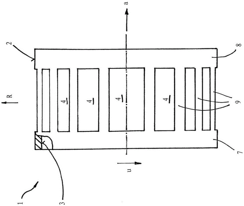
[0035] The drawing shows a side view of a rolling bearing cage 1 which is used in cylindrical roller bearings. The cage 1 has two side rings 7 and 8 , which are connected to one another by a plurality of transverse beams 9 . The transverse beam 9 extends along the axial direction a. The pockets 4 for the rolling elements, here cylindrical rollers, are formed between the transverse beam 9 and the side rings 7 , 8 . Cage 1 is designed in one piece as an injection-molded part.

[0036] The cage 1 thus has an annular structure, characterized by a radially outer surface 2 and a radially inner surface 3 (the radially inner surface 3 is located at figure 1 shown in partial cross-section).

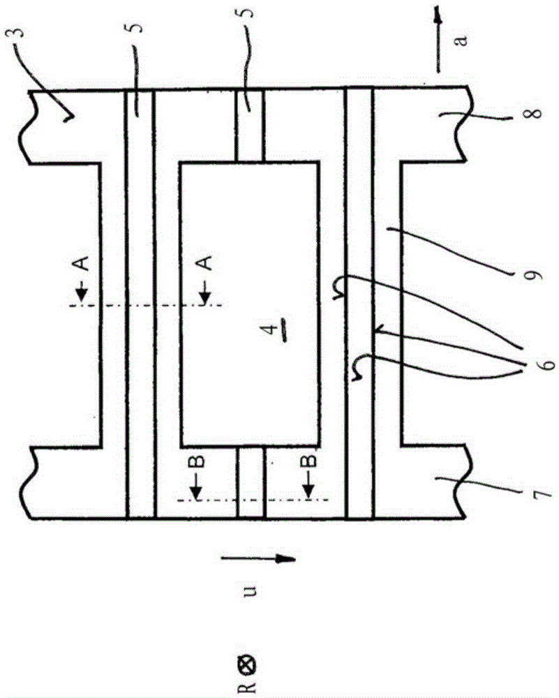
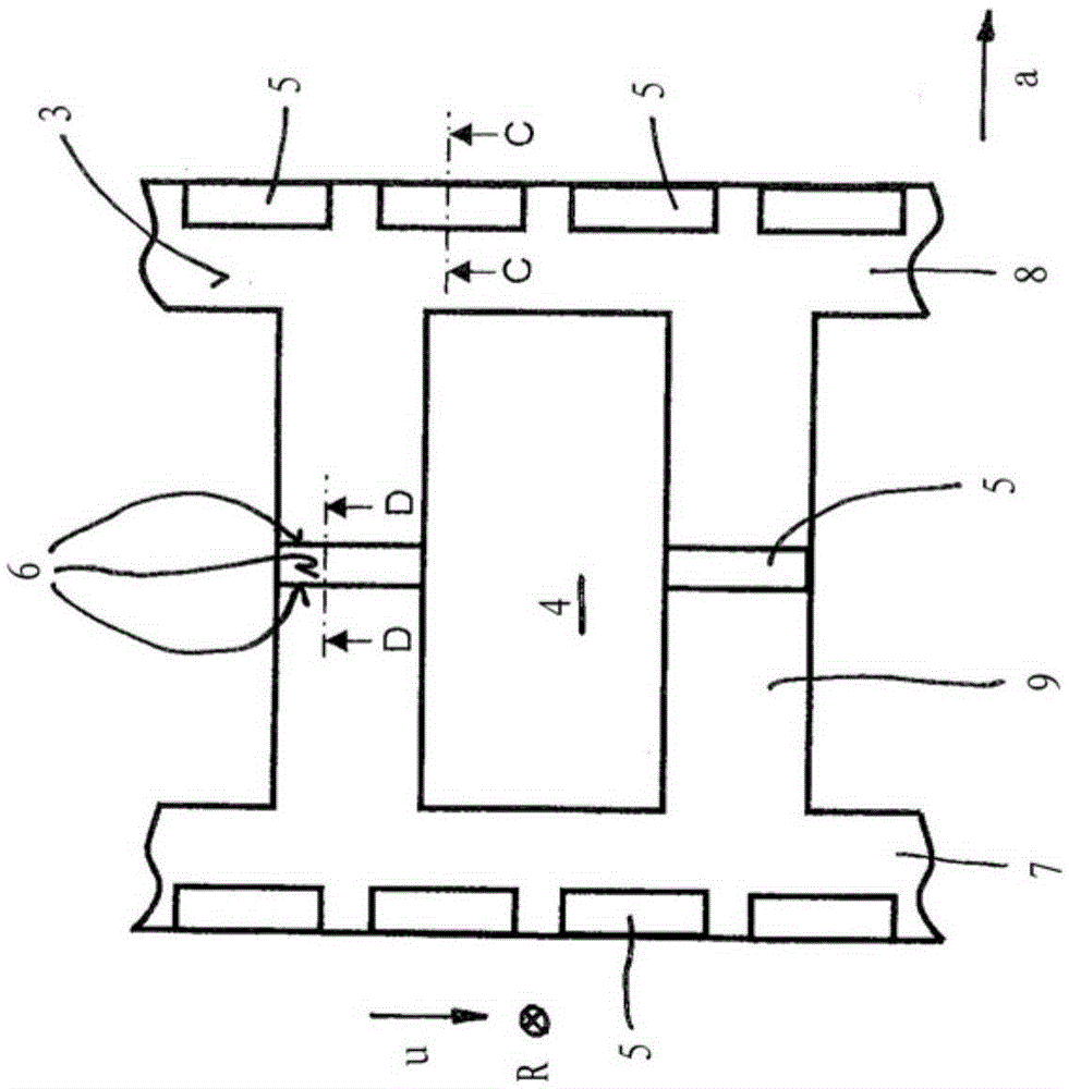
[0037] Observing the part of the cage 1 from the inside, that is, along the radial direction R, it can be seen as follows figure 2 and 3 Shown are parts for two alternative solutions.

[0038] As shown, on the radially inner surface 3 a projection 5 is formed, which extends towards the spac...


PUM


Abstract

The invention relates to a rolling element bearing cage (1) comprising an annular element that has a radially outer-lying surface (2) and a radially inner-lying surface (3), with receiving pockets (4) for rolling elements designed in said annular element. In order to improve the lubrication of said rolling element bearing, the invention suggests that, on said radially inner-lying surface (3), at least one radially inward-extending projection (5) is arranged that extends into the space delimited by said inner-lying surface (3) and forms a free surface (6) in this space.

Description

technical field [0001] The invention relates to a rolling bearing cage comprising a ring element having a radially outer surface and a radially inner surface, pockets for rolling bodies being formed in the ring element. Background technique [0002] Rolling bearing cages of this type have been known for a long time. Mostly they consist of two side rings connected to each other by a plurality of transverse beams. Pockets for the rolling elements are formed between the beams. For lubrication, grease is added to the space between the inner and outer rings of the bearing. [0003] Especially in fast-rotating rolling bearings there is the problem that the distribution of grease in the rolling bearing is locally subject to severe fluctuations before, during and after the operating process. At higher rotational speeds, there is a lack of lubrication in rolling bearings primarily in the sliding contact and thus in the region of the cage pockets. At correspondingly high rotationa...

Claims


Application Information

Patent Timeline
Patent Type & Authority Applications(China)
IPC IPC(8): F16C33/46F16C33/66
CPCF16C33/4635F16C33/4611F16C33/4676F16C33/6629F16C2220/04
Inventor J.阿斯曼T.克劳斯
Owner AB SKF
Learn More