
Device and process for generation of electrical energy

A technology of electric energy and power supply, applied in the field of cosmic particles

Inactive Publication Date: 2016-03-02
ARION TECHA BRASIL TAO DE ATIVOS
View PDF3 Cites 0 Cited by
  • Summary
  • Abstract
  • Description
  • Claims
  • Application Information

AI Technical Summary

Problems solved by technology

However, as mentioned in the title of the above patent, the said patent is only about the detection of muon, not the captivator of the intrinsic energy of muon

Method used


Image

  • Device and process for generation of electrical energy
  • Device and process for generation of electrical energy
  • Device and process for generation of electrical energy

Examples


Embodiment 1

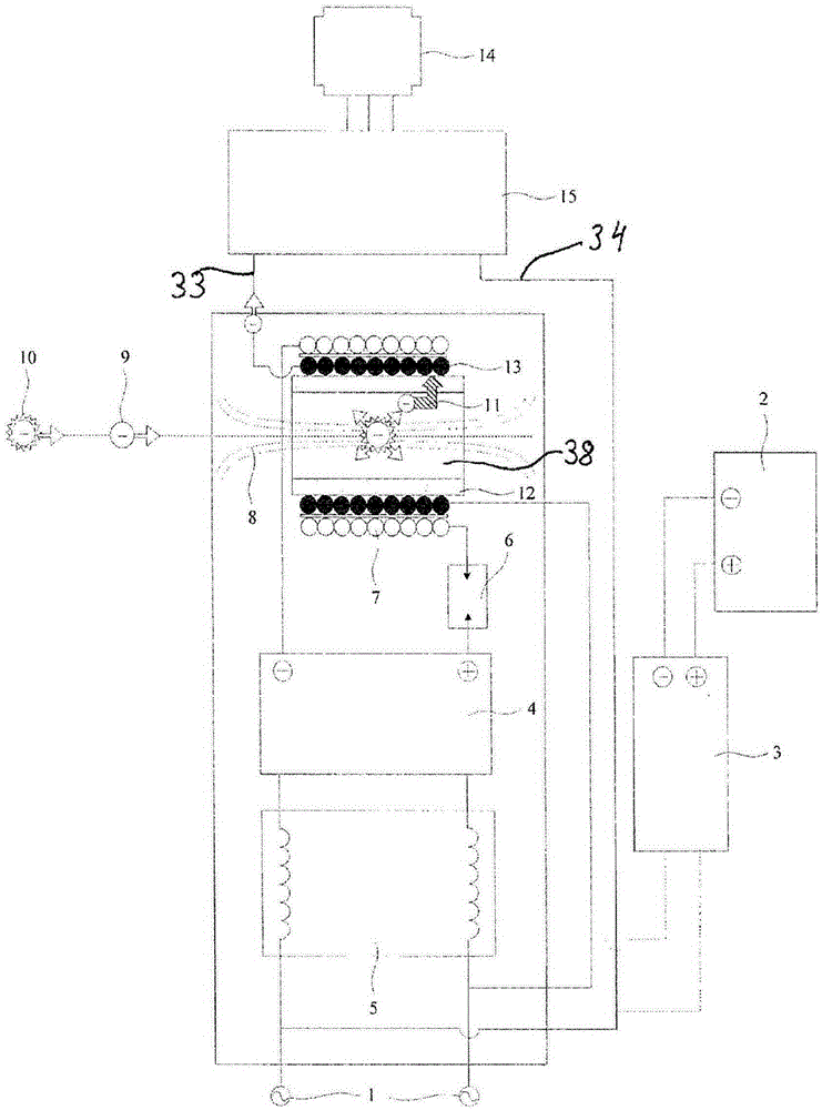
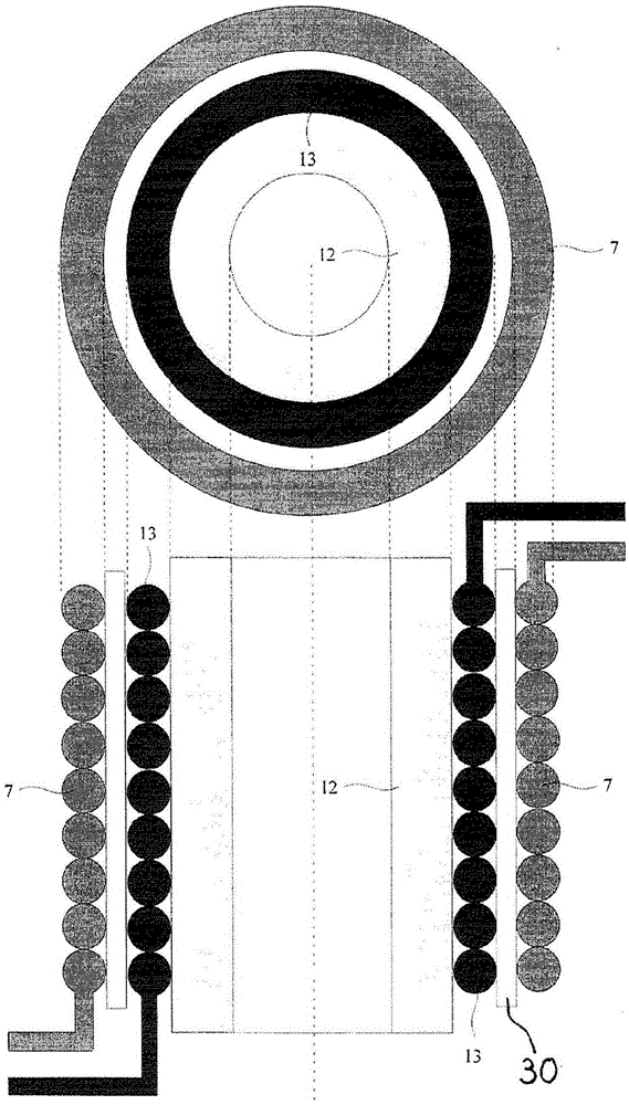
[0051] A commercial battery of 9V and 0.1A (thus 0.9W) connected with an external coil 7 of length 25cm and a copper wire of 3mm with a radius of 5cm figure 1the device described. The inner coil is also made of copper, with 5 mm traces and a radius of approximately 4 cm. The "chip" or integrated circuit PIC (32) (Programmable Integrated Circuit) is programmed to operate at the above-mentioned wavelength λ in the oscillator 4 B oscillation. As an example only, a Hartley type oscillator may be used. has been preprogrammed to emit the lambda defined above B The "PIC" 32 insert Figure 5 middle. The load used in the experiment consisted of fifteen 110V, 60W bulbs, so the total charge was 900W. It is very unexpected that all bulbs have illuminance and normal brightness to the naked eye after being lit. This results in a COP of 1000 due to the extraction of muons in the atmosphere.

Embodiment 2

[0053] refer again figure 1 , In this embodiment, the power supply 1 is composed of a 110V and 19A home network. The power measured at the outputs 33, 34 was 40000V and 19A. This represents a 380-fold increase in power. The data are presented in Table 1 above. Apparently, this unexpectedly high increase originates from the energy of the muon electrons.


PUM


Abstract

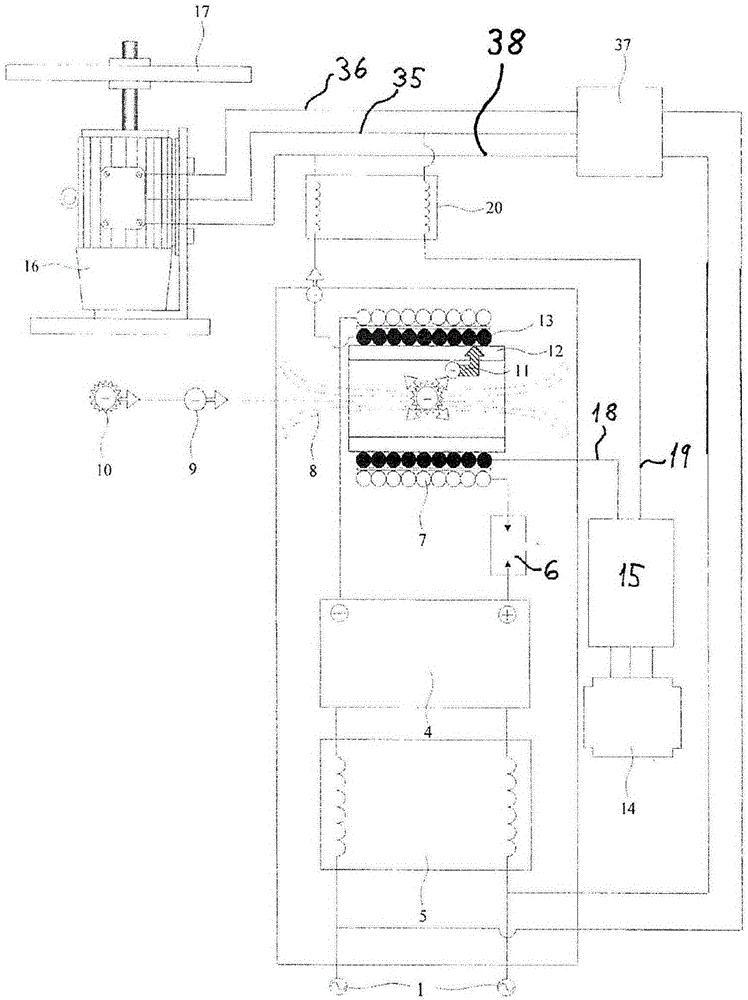
The present invention refers to a muonic electromagnetic generator to be utilized for purposes of generating electrical energy, whose generator is connectable to at least one source of electric energy (1; 2) with a lower power than the power generated by the said generator. The generator according to the invention comprises: a) at least one outer electric coil (7) b) at least one inner electric coil (13), situated substantially inside the outer electric coil (7); and c) an oscillator (4). The oscillator (4) is connected between the said source of electrical energy (1; 2) and the said outer electric coil (7). When the outer electric coil is connected to a source of electric energy (1 or 2) via an oscillator (4) that was previously tuned to emit a frequency corresponding to a certain fraction specific to the Compton frequency of a muon, the muonic energy is absorbed by an inner electric coil (13), and this energy can be used to feed any external load (14). This muonic energy can be significantly greater than the power of the source of energy (1; 2).

Description

technical field [0001] The present invention relates to a device and a method for generating electrical energy by means of the decay of muons (μ), which are derived from cosmic particles called pions. Background technique [0002] Although having the same spin (1 / 2) and the same charge, muons are elementary particles with a mass about 200 times larger than electrons, and are called "second generation partners" of electrons. The muons were discovered in cosmic rays in 1937. The particles are not affected by strong interactions and only participate in weak and electromagnetic interactions. The muon is very unstable and has 2·10 -6 lifetime, and typically decays in electrons, μ-neutrinos, and electron-neutrinos. As far as is known, a photon generator, also known as a solar cell, can capture light particles called photons from the sun (solar panel) and convert the light particles into electrical energy, such as US Patent Document No. 20090127773 . However, the technology su...

Claims


Application Information

Patent Timeline
Patent Type & Authority Applications(China)
IPC IPC(8): H02N11/00G21H7/00H02M11/00
CPCG21H7/00H02N11/008H02K11/30H02K3/28H02K11/0094
Inventor 热尔松·西尔瓦-派瓦塞巴斯蒂昂·弗洛伦蒂诺-西尔瓦
Owner ARION TECHA BRASIL TAO DE ATIVOS
Learn More