Anti-blocking efficient shakeout hopper for dry-sand full mold casting

A solid mold casting, anti-clogging technology, applied in foundry molding equipment, machinery for cleaning/processing mold materials, manufacturing tools, etc., can solve the problems of low sand falling efficiency, high labor intensity, etc. , The effect of improving discharging efficiency, reducing labor intensity and labor cost

Inactive Publication Date: 2016-03-09
WUXI XINMAO FORGING CO LTD
8 Cites 0 Cited by

AI-Extracted Technical Summary

Problems solved by technology

The above-mentioned anti-clogging method has high ...

Abstract

The invention relates to an anti-blocking efficient shakeout hopper for dry-sand full mold casting. The anti-blocking efficient shakeout hopper for dry-sand full mold casting comprises a hopper body. The lower end of the hopper body is provided with a discharging outlet. A supporting sleeve is mounted on the outer side of the discharging outlet, and a material guide sleeve is mounted on the inner side of the supporting sleeve. The material guide sleeve is rotationally mounted between the lower end of the discharging outlet and an infolded ring of the supporting sleeve through a thrust bearing, and rolling balls are mounted in a ring groove in the upper surface of the infolded ring. A driven gear ring is arranged on the outer wall of the material guide sleeve. A motor is mounted on the side face of the supporting sleeve through a support. A driving gear engaged with the driven gear ring is mounted on a driving shaft of the motor. A supporting base is mounted in the material guide sleeve through a plurality of supporting rods. A stirring shaft is mounted on the supporting base, and a stirring blade is spirally mounted on the stirring shaft. A control box is mounted on the outer wall of the supporting sleeve, and a timing controller and a forward and backward rotation controller of the motor are mounted in the control box and are electrically connected with each other.

Application Domain

Technology Topic

Full-mold castingDry sand +2

Image

  • Anti-blocking efficient shakeout hopper for dry-sand full mold casting

Examples

  • Experimental program(1)

Example Embodiment

[0010] The specific embodiments of the present invention will be further described below in conjunction with the accompanying drawings.
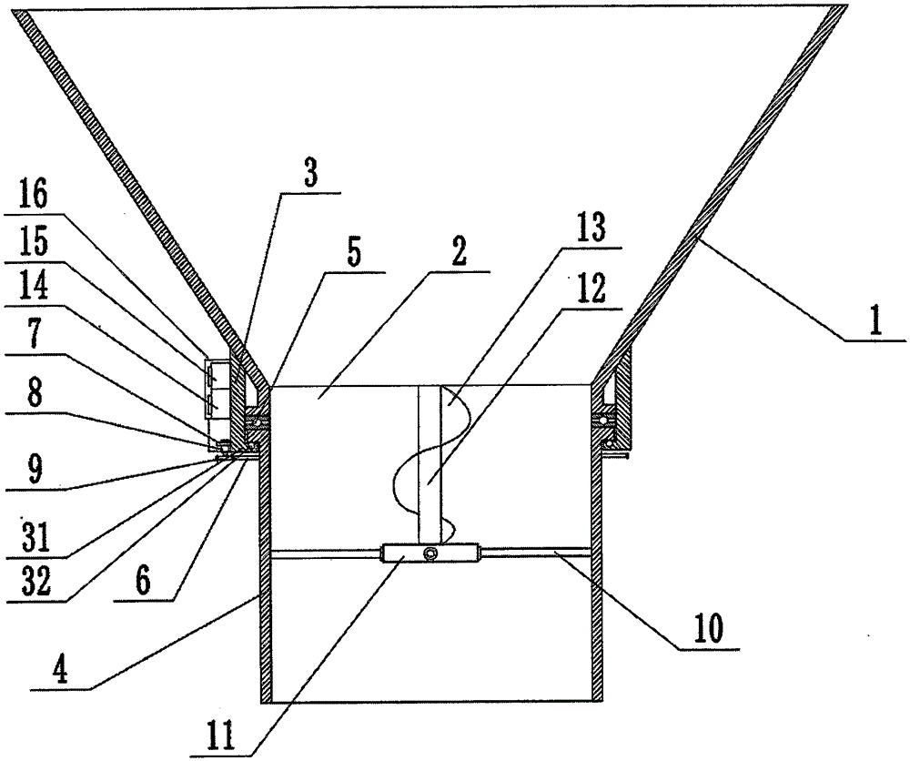
[0011] Such as figure 1 As shown, the sand falling hopper for casting production of this embodiment includes a hopper body 1. The lower end of the hopper body 1 is provided with a discharge port 2. A support sleeve 3 is installed outside the discharge port 2, and a support sleeve 3 is installed inside the support sleeve 3 The guide sleeve 4 is rotatably installed between the lower end of the discharge port 2 and the inner folding ring 31 of the support sleeve 3 through the thrust bearing 5, and the ball 32 is installed in the ring groove on the upper surface of the inner folding ring 31; The outer wall of the material sleeve 4 is provided with a driven gear ring 6, the side of the support sleeve 3 is equipped with an external drive motor 8 through a bracket 7, and a driving gear 9 meshing with the driven gear ring 6 is installed on the drive shaft of the external drive motor 8; A supporting seat 11 is installed in the guide sleeve 4 through a plurality of supporting rods 10, an agitating shaft 12 is installed on the upper side of the supporting seat 11, a rotating agitating sheet 13 is installed on the agitating shaft 12, and the lower side of the supporting seat 11 is installed The inner driving motor 14 connected with the stirring shaft 12, the inner driving motor 14 is installed with a motor protection cover 15; the driving directions of the inner driving motor 14 and the outer driving motor 8 are opposite; the outer wall of the supporting sleeve 3 is installed with a control box 18 to control A timing controller 17 electrically connected to each other and a forward and reverse controller 16 of the outer drive motor 8 and the inner drive motor 14 are installed in the box 18.
[0012] When the present invention is working, the motor 8 drives the driving gear 9, the driving gear 9 drives the driven gear ring 6, the driven gear ring 6 drives the guide sleeve 4 to rotate, and the stirring shaft 12 and the stirring blade 13 in the guide sleeve 4 rotate to achieve Stir the sand to avoid blocking the discharge port 2; the timing controller 15 sets the time, and the forward and reverse rotation of the motor 8 is controlled by the forward and reverse controller 14, and the forward and reverse rotation of the stirring shaft 12 and the stirring piece 13 , To further ensure that the discharge port 2 is not blocked.
[0013] The above-mentioned embodiments are the preferred embodiments of the present invention. They are only used to facilitate the description of the present invention, and are not intended to limit the present invention in any form. Anyone with ordinary knowledge in the technical field, if they do not deviate from the provisions of the present invention Within the scope of the technical features, the equivalent embodiments with partial changes or modifications made by using the technical content disclosed in the present invention without departing from the technical features of the present invention still fall within the scope of the technical features of the present invention.

PUM

no PUM

Description & Claims & Application Information

We can also present the details of the Description, Claims and Application information to help users get a comprehensive understanding of the technical details of the patent, such as background art, summary of invention, brief description of drawings, description of embodiments, and other original content. On the other hand, users can also determine the specific scope of protection of the technology through the list of claims; as well as understand the changes in the life cycle of the technology with the presentation of the patent timeline. Login to view more.

Similar technology patents

Pole piece feeding device

Owner:GUANGDONG YI XINFENG INTELLIGENT EQUIP CO LTD

Classification and recommendation of technical efficacy words

People also interested in

Why Eureka
Try Eureka