Locking mechanism of overturning clamp

A technology of locking mechanism and overturning fixture, applied in the direction of manufacturing tools, auxiliary devices, auxiliary welding equipment, etc., can solve the problems of large impact force, inability to completely solve the problems of invisible solder joints, ergonomics, and potential safety hazards. The effect of improving accuracy

Inactive Publication Date: 2016-03-09
CHERY AUTOMOBILE CO LTD
View PDF5 Cites 6 Cited by
  • Summary
  • Abstract
  • Description
  • Claims
  • Application Information

AI Technical Summary

Problems solved by technology

[0004] This locking mechanism can only provide one or two states for the fixture or the inspection console, and there are limitations in the flipping process, which leads to the inability to completely solve the problems of invisible solder joints and ergonomics
For example, in the stud welding station, some welding sub-assemblies need to be stud welded on both sides. Due to the limitation of this turning mechanism, the operator needs to walk back and forth on both sides to weld, which is labor intensive and has Security risks
In addition, the locking mechanism is controlled by a pneumatic system. When the fixture is turned over, the impact force is large, and there is a safety hazard in the process of inserting and pulling out the pin.

Method used


Image

  • Locking mechanism of overturning clamp
  • Locking mechanism of overturning clamp
  • Locking mechanism of overturning clamp

Examples


Embodiment Construction

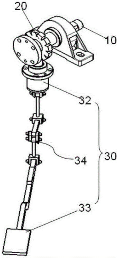
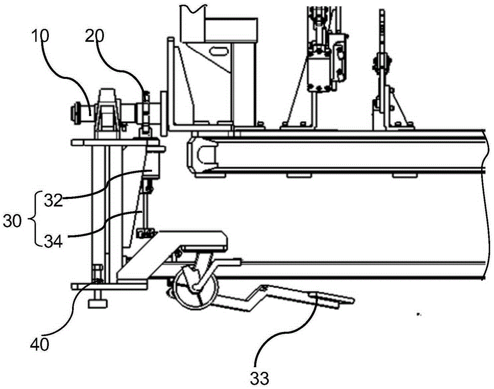
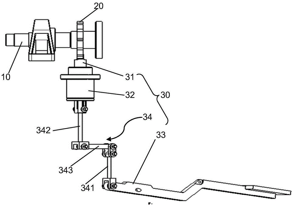
[0012] A locking mechanism for an overturning jig, comprising an indexing plate 20 fixed on the overturning shaft 10 of the fixture and a drive unit 30 fixed on the side of the fixture, the said indexing plate 20 is provided with two More than one indexing groove 21, the side of the indexing groove 21 is provided with a latch 31, the drive unit 30 drives the latch 31 to be inserted in the indexing groove 21 or the driving latch 31 is in a position to avoid the indexing groove 21 .

[0013] Such as figure 1 and 4 As shown, indexing grooves 21 arranged along the radial direction are arranged on the edge of the indexing plate 20, and the number and positions of the indexing grooves 21 are determined according to the specific use requirements of the clamp. What needs to be explained here is that the clamp turning axis 10 refers to the rotating shaft around which the fixture rotates, and the indexing plate 20 is arranged on the turning axis 10, and the indexing plate 20 rotates t...


PUM


Abstract

The invention relates to the field of automobile auxiliary production equipment, in particular to a locking mechanism of an overturning clamp. The locking mechanism comprises a dividing plate fixed to a clamp overturning shaft and a driving unit fixed beside the clamp. The dividing plate is provided with two or more dividing grooves in the circumferential direction of the edge of the dividing plate at intervals, and plug pins are arranged beside the dividing grooves. The driving unit drives the plug pins to be inserted into the dividing grooves or drives the plug pins to be located in the positions avoiding the dividing grooves; when the plug pins are located in the positions avoiding the dividing grooves, the overturning clamp can freely rotate around the clamp overturning shaft, when the clamp rotates to a moderate position, the driving unit drives the plug pins to be inserted into the dividing grooves, and at the moment, the plug pins limit the dividing grooves and the overturning shaft cannot rotate, so that a workpiece is welded in a clamp stable state, and overturning action of the clamp is achieved. The number and the positions of the dividing grooves can be determined according to the positions where the clamp needs to stay, the multi-angle overturning requirement of the clamp is met, and the problem that welding positions are invisible is completely solved.

Description

technical field [0001] The invention relates to the field of automobile auxiliary production equipment, in particular to a locking mechanism for a turning fixture. Background technique [0002] At present, the tooling used for positioning workpieces in various welding workshops of automobile factories is mainly fixtures. Through the fixture, the workpiece can be quickly and accurately positioned and supported and maintained properly, so that all the workpieces produced can be fixed within a specific range, ensuring the precision and interchangeability of the products. Usually, fixtures are designed as static mechanisms, but in order to ensure the safety and convenience of operation, some fixtures need to be designed as dynamic mechanisms, such as axial flipping. At present, the turning system arranged in the welding shop in the fixture can make the fixture turn 90° in the axial direction around its turning axis. This can solve or reduce welding defects caused by invisible ...

Claims


Application Information

Patent Timeline
Patent Type & Authority Applications(China)
IPC IPC(8): B23K37/047
CPCB23K37/047
Inventor 程娟吴叶茂肖新李敏
Owner CHERY AUTOMOBILE CO LTD
Why Eureka
Try Eureka