Air pressure flexible clamping device of frame-shaped parts with thin walls, and clamping method of air pressure flexible clamping device

A technology of clamping device and air pressure, which is applied in the direction of workpiece clamping device, clamping device, positioning device, etc., can solve the problems of deformation, high cost and machining accuracy error of thin-walled frame parts, and achieve high flexibility, Strong dimensional applicability and guaranteed stability

Inactive Publication Date: 2016-03-09
UNIV OF SHANGHAI FOR SCI & TECH
View PDF4 Cites 32 Cited by
  • Summary
  • Abstract
  • Description
  • Claims
  • Application Information

AI Technical Summary

Problems solved by technology

The disadvantages of this clamping method are: 1) Since the thin-walled parts are closely attached to the rubber, it is impossible to achieve effective control of the machining accuracy of the parts; 2) In addition, due to the deformation rate of the airbag, therefore Clamping of thin-walled parts that cannot meet irregular shapes
Although this clamping method is simple, its obvious disadvantage is that the traditional clamp can easily cause deformation of thin-walled frame parts due to its inability to control its clamping force, resulting in large errors in machining accuracy.
[0008] 1) The degree of flexibility is not high, the shape of the processed parts is relatively limited, and the rough and fine machining methods are limited
[0009] 2) The fixture adjustment time is long, the cost is high, and the clamping force is difficult to adjust and control
[0010] 3) The adaptability is poor, the adjustment of the fixture is too dependent on experience, and the accuracy is difficult to control

Method used


Image

  • Air pressure flexible clamping device of frame-shaped parts with thin walls, and clamping method of air pressure flexible clamping device
  • Air pressure flexible clamping device of frame-shaped parts with thin walls, and clamping method of air pressure flexible clamping device
  • Air pressure flexible clamping device of frame-shaped parts with thin walls, and clamping method of air pressure flexible clamping device

Examples


Embodiment 1

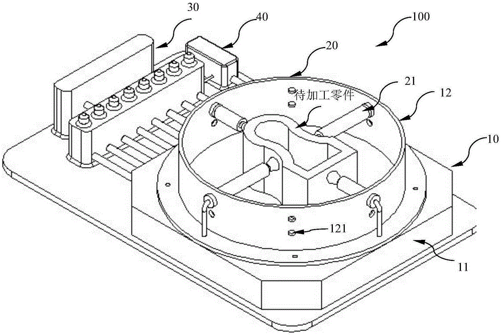
[0036] figure 1 It is a three-dimensional schematic diagram of the structure of the air pressure flexible clamping device for thin-walled frame parts in this embodiment

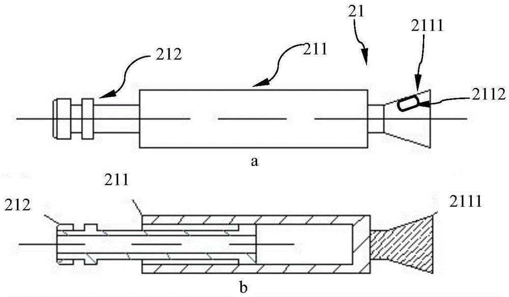
[0037] figure 2 It is a structural schematic diagram of the air pressure clamping part of the air pressure flexible clamping device for thin-walled frame parts in this embodiment

[0038] Such as figure 1 , shown in 2, the air pressure flexible clamping device 100 of thin-walled frame parts includes: a support unit 10, a clamping unit 20 arranged on the support unit 10, a pneumatic unit 30 communicated with the clamping unit 20 (including the same clamp The connecting pipeline 31 communicating with the holding unit 20) and the control unit 40 controlling the pneumatic unit 30. in,

[0039] The support unit 10 includes a base 11 and a closed-loop support 12 for enclosing the part to be processed,

[0040] The closed-loop bracket 12 is a rigid ring, which is fixed on the base 11 by welding, etc., and the ...


PUM


Abstract

An air pressure flexible clamping device of frame-shaped parts with thin walls is used for clamping and fixing of to-be-machined frame-shaped parts with thin walls and cylinder body parts when being machined, and comprises a support unit which comprises a base and a closed-ring support which is arranged on the base and is used for surrounding the to-be-machined parts; a clamping unit which is arranged on the wall of the closed-ring support, and comprises at least three air pressure clamping parts which are mutually cooperated for clamping and fixing the to-be-machined parts; a pneumatic unit which is communicated with the air pressure clamping parts for respectively controlling air pressure of multiple air pressure clamping parts, wherein the air pressure clamping parts are detachably connected on the closed-ring support, a head end is provided with a suction nozzle, the suction nozzle is in contact, clamped and fixed with the outer surface of each of the to-be-machined parts through negative pressure. The invention also provides a clamping method. The device and the method have the advantages of being flexible in operation, high in applicability to shapes and sizes of thin-walled workpieces, and capable of effectively ensuring the stability, accuracy and reliability of the clamping of the frame-shaped parts with thin walls during a machining process.

Description

technical field [0001] The invention belongs to the field of mechanical devices, in particular to a processing and clamping device for thin-walled frame parts used in the fields of automobiles, aerospace and key precision processing. Background technique [0002] The processing of thin-walled parts in the field of mechanical processing is an unbreakable problem. With the increasing demand for small batches and many varieties of thin-walled parts in the current market, the cost of fixtures and processing will increase. In order to meet the needs of flexible thin-walled parts processing, especially to solve the problem of clamping design for thin-walled parts processing, this patent is mainly aimed at the processing of thin-walled frame parts. In the process of processing thin-walled frame parts, due to their special shape and low rigidity, the primary technical difficulty in processing is the clamping of thin-walled frame parts. The characteristics of thin-walled frame parts...

Claims


Application Information

Patent Timeline
Patent Type & Authority Applications(China)
IPC IPC(8): B25B11/00B23Q3/08
CPCB23Q3/088B23Q2703/10B25B11/005
Inventor 江小辉汪中厚张振亚李郝林
Owner UNIV OF SHANGHAI FOR SCI & TECH
Why Eureka
Try Eureka