Cylinder body water jacket with orifice plug and engine cylinder body

A cylinder water jacket and throttle plug technology, applied in the direction of engine components, machines/engines, cylinders, etc., can solve the problems of reducing coolant flow rate and water pressure, uneven coolant flow, and reducing cooling effect, etc., to achieve improved Flow rate and water pressure, improved cooling effect, uniform flow effect

Active Publication Date: 2016-03-09
CHONGQING LONCIN ENGINE
View PDF8 Cites 2 Cited by
  • Summary
  • Abstract
  • Description
  • Claims
  • Application Information

AI Technical Summary

Problems solved by technology

[0002] The cylinder block water jacket is a coolant circulation channel designed inside the engine to cool down the high-temperature parts of the engine. The coolant circulates in the water jacket to achieve the effect of heat dissipation. The structure of the water jacket has a great influence on the circulation of the coolant. Existing The engine coolant circulation method is as follows: first, the water pump presses the coolant from the water inlet at the front end of the cylinder block and enters the annular flow channel around the cylinder hole, and the coolant splits to both sides at the entrance of the annular flow channel to cool separately Therefore, in the existing engine, after the coolant enters the annular flow channel, it first cools the cylinder near the water inlet, and then cools the other cylinders in order. During the coolant circulation, there is no cooling For the rear cylinder, part of the coolant directly enters the cylinder head water jacket, which will cause less coolant flowing through the rear cylinder than the front cylinder, uneven coolant flow, and poor cooling effect. On the other hand, due to After the coolant enters the annular flow channel, it will divert to both sides of the flow channel, thereby greatly reducing the flow rate and water pressure of the coolant, thereby reducing the cooling effect;

Method used


Image

  • Cylinder body water jacket with orifice plug and engine cylinder body
  • Cylinder body water jacket with orifice plug and engine cylinder body
  • Cylinder body water jacket with orifice plug and engine cylinder body

Examples


Embodiment Construction

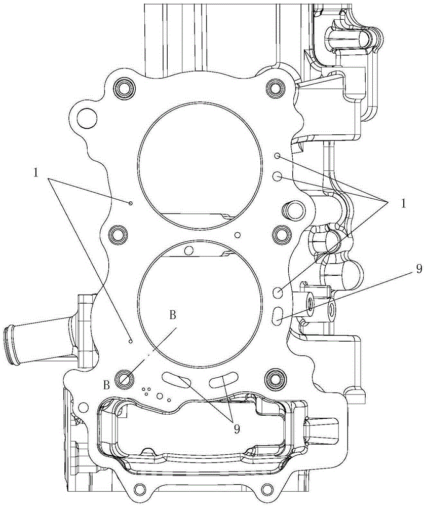
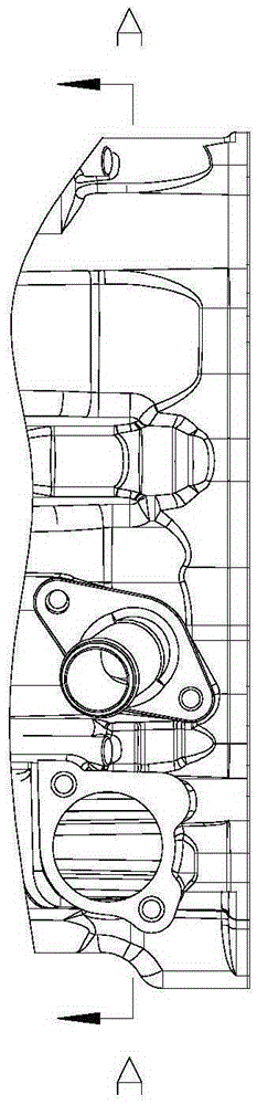
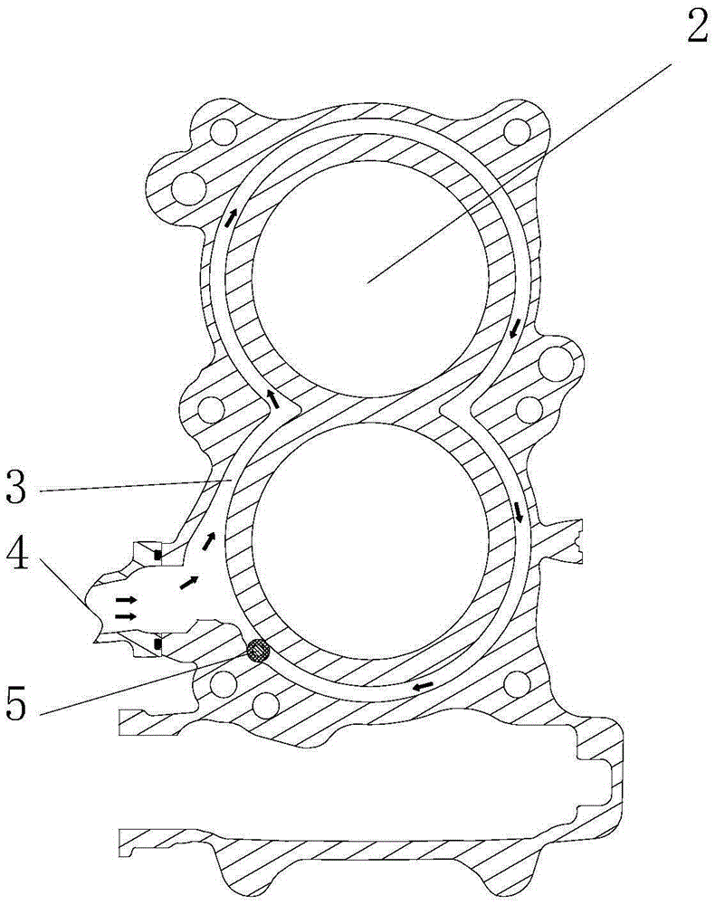
[0019] figure 1 It is a structural schematic diagram of the present invention; figure 2 for figure 1 left view of image 3 for figure 2 Sectional view at A-A in the middle. As shown in the figure, the cylinder water jacket with a throttle plug in this embodiment includes an annular flow channel 3 arranged around each cylinder hole 2 and a water inlet 4 communicated with the annular flow channel 3 and arranged in the cylinder body. Water outlet; the annular flow channel 3 is provided with a throttling plug 5 that allows the cooling liquid to flow in one direction along the annular channel 3. Thereby blocking a flow channel of the cooling liquid, so that the cooling liquid can only go around the annular flow channel 3 one-way flow channel (that is, flow clockwise or counterclockwise around the annular flow channel 3), because a part of the cooling liquid needs to flow away from the water inlet The cylinder block at the 4th end enters into the water jacket of the cylinder ...


PUM


Abstract

The invention discloses a cylinder body water jacket with an orifice plug. The cylinder body water jacket comprises an annular runner, a water inlet and a water outlet, wherein the annular runner is arranged around all steam cylinder holes; the water inlet and the water outlet are formed in a cylinder body and communicated with the annular runner; the orifice plug allowing cooling liquid to flow in single direction along the annular runner is disposed in the annular runner. By means of the cylinder body water jacket with the orifice plug, the flow of the cooling liquid passing through the side walls of all the cylinder holes in the cylinder body can be kept uniform, and the flow speed and pressure of the cooling liquid can be effectively increased so as to improve the cooling effect of an engine.

Description

technical field [0001] The invention relates to the field of engine components, in particular to a cylinder body water jacket with a throttling plug. Background technique [0002] The cylinder block water jacket is a coolant circulation channel designed inside the engine to cool down the high-temperature parts of the engine. The coolant circulates in the water jacket to achieve the effect of heat dissipation. The structure of the water jacket has a great influence on the circulation of the coolant. Existing The engine coolant circulation method is as follows: first, the water pump presses the coolant from the water inlet at the front end of the cylinder block and enters the annular flow channel around the cylinder hole, and the coolant splits to both sides at the entrance of the annular flow channel to cool separately Therefore, in the existing engine, after the coolant enters the annular flow channel, it first cools the cylinder near the water inlet, and then cools the othe...

Claims


Application Information

Patent Timeline
Patent Type & Authority Applications(China)
IPC IPC(8): F02F1/16
Inventor 阳远贵胡义强杨生华梁辉陈翔周良兵王桂丹
Owner CHONGQING LONCIN ENGINE
Why Eureka
Try Eureka