
A salt pond remote control electric gate lifting mechanism

A lifting mechanism and remote control technology, which is applied to engine components, sliding valves, mechanical equipment, etc., can solve the problems of unusable gate valves, large area occupied by salt ponds, and difficult operation, so as to save installation space and improve anti-corrosion performance , the effect of high control precision

Active Publication Date: 2018-04-06
TIANJIN BOYADA TECH
View PDF6 Cites 0 Cited by
  • Summary
  • Abstract
  • Description
  • Claims
  • Application Information

AI Technical Summary

Problems solved by technology

The reason is that the corrosion is severe in the brine environment, so ordinary gate valves cannot be used after being corroded.
In addition, because the salt ponds (regulation ponds, evaporation ponds, and crystallization ponds) in general saltworks occupy a large area and the environment is harsh, it is quite difficult to realize automatic operation of valves in saltworks, and it is also a practical problem that saltworks urgently need to solve

Method used


Image

  • A salt pond remote control electric gate lifting mechanism
  • A salt pond remote control electric gate lifting mechanism
  • A salt pond remote control electric gate lifting mechanism

Examples


Embodiment Construction

[0025] The present invention will be further described in detail below through the specific examples, the following examples are only descriptive, not restrictive, and cannot limit the protection scope of the present invention with this.

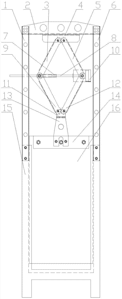
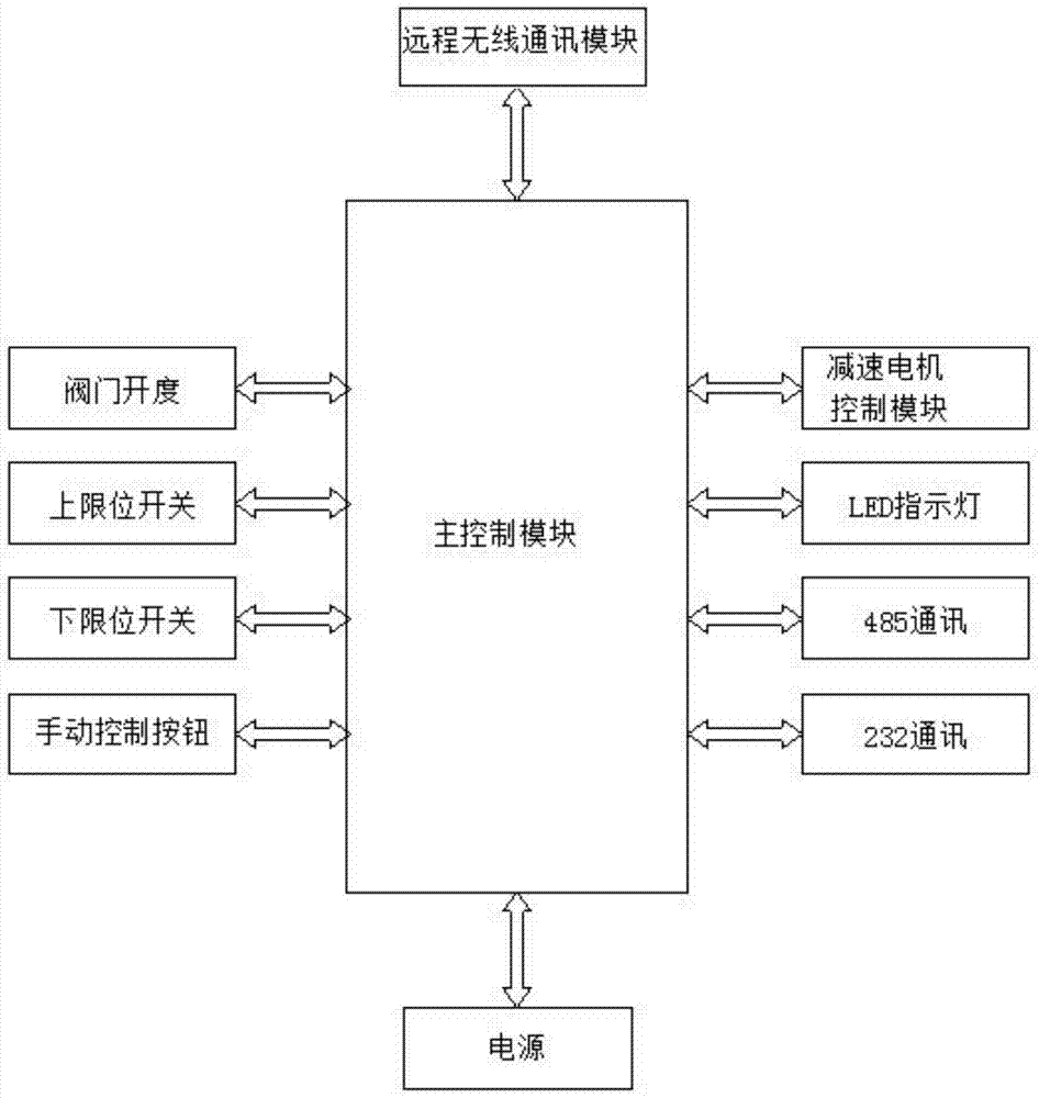
[0026] A salt pond remote control electric gate lifting mechanism, which includes a steel door frame installed on a wooden gate, a lifting mechanism and a control unit. The steel door frame is fixedly formed by left steel column 1, right steel column 6 and steel beam frame 2. The wooden gate unit comprises a wooden gate frame 15, a gate beam 14 and a wooden gate plate 16, and the steel gate frame is fixedly connected to the wooden gate frame top. The left steel column and the right steel column of the steel door frame are fixedly installed with the wooden gate frame. The lifting mechanism is installed on the steel door frame. The upper part of the wooden gate is fixedly installed with the beam of the gate, and the two sides of the wooden g...


PUM


Abstract

The invention relates to a lifting mechanism for a remote control electric gate of a salt pond. The lifting mechanism for the remote control electric gate of the salt pond is characterized in that the lifting mechanism comprises a steel gate frame, a lifting mechanism body and a control unit, wherein the steel gate frame, the lifting mechanism body and the control unit are installed on a wooden gate unit; the wooden gate unit comprises a wooden gate frame, a wooden gate plate and a gate plate cross beam; the steel gate frame is fixedly connected to the upper portion of the wooden gate frame; the lifting mechanism body is installed on the steel gate frame; the upper portion of the wooden gate plate and the gate plate cross beam are fixedly installed; the two sides of the wooden gate plate are installed in the wooden gate frame in a guiding mode; the upper portion of the wooden gate plate is connected with the lifting mechanism body through the gate plate cross beam and is driven by the lifting mechanism body to go up and down in the wooden gate frame; the lifting mechanism body is controlled by the control unit. According to the lifting mechanism for the remote control electric gate of the salt pond, the design is scientific and reasonable; the remote control of the gate of the salt pond can be achieved; the lifting mechanism has the advantages of being stable in structure, smooth in operation, easy to control and long in service life, is especially suitable for severe environments of the salt pond, and has good application prospects.

Description

technical field [0001] The invention relates to an automatic control device for gate valves in salt ponds, in particular to a remote control electric gate lifting mechanism for salt ponds. Background technique [0002] For many years, the opening and closing of the brine gates in the brine ponds (adjustment ponds, evaporation ponds, and crystallization ponds) in the brine production process in the salt industry have been manually operated. The brine production process is automated, and only the experience of the brine workers can be used to operate the brine making valves to carry out salt production, which greatly restricts the development of the salt industry. [0003] Ordinary gate valves cannot be used in the harsh environment of the salt field, and wooden gates have been used for many years. The reason is that the corrosion is serious in the environment of bittern, so the general gate valve will not be used after corrosion. In addition, because the salt ponds (regulat...

Claims


Application Information

Patent Timeline
Patent Type & Authority Patents(China)
IPC IPC(8): F16K3/02F16K3/30F16K31/04F16K31/44
CPCF16K3/0281F16K3/30F16K31/04F16K31/44
Inventor 范树礼
Owner TIANJIN BOYADA TECH
Learn More