Intelligent track camera robot system
A robot system and camera technology, applied in the direction of supporting machines, mechanical equipment, machines/supports, etc., can solve the problems of high manufacturing cost and maintenance cost, complex adjustment mechanism structure, and non-adjustable height, and achieve production cost and maintenance cost. The effect of low, simple lifting structure and fast adjustment speed
- Summary
- Abstract
- Description
- Claims
- Application Information
AI Technical Summary
Problems solved by technology
Method used
Image
Examples
Embodiment 1
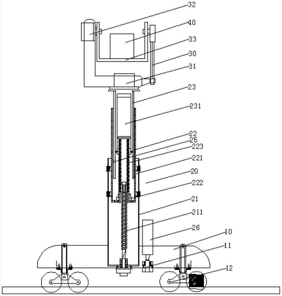
[0020] A kind of intelligent track camera robot system, comprises rail car 10, lifting mechanism 20 and cloud platform 30, camera 40 is placed on the platform 30, and described lifting mechanism 20 comprises first lifting column 21, second lifting column 22 and the third Lifting columns 23, the third lifting column 23 is set in the second lifting column 22, the second lifting column 22 is set in the first lifting column 21; the rail car 10 is provided with rail wheels 12, and the rail car is fixed with a horizontal The moving motor 11 and the vertical motor 26, the horizontal moving motor 11 drives the rail wheel 12 to move, and the vertical motor 26 drives the elevating mechanism 20 to perform lifting motion.
[0021] The cloud platform 30 is a two-axis platform, and the two-axis platform is provided with a vertical rotating shaft and a vertical rotating shaft drive motor 32, a horizontal rotating shaft and a driving motor 31 of the horizontal rotating shaft, and is fixedly co...
Embodiment 2
[0025] This embodiment is identical with embodiment 1 except following feature:
[0026] The vertical rotation shaft is provided with a limit structure, and the maximum angle of rotation of the vertical rotation shaft is limited to 120°.
Embodiment 3
[0028] This embodiment is identical with embodiment 1 except following feature:
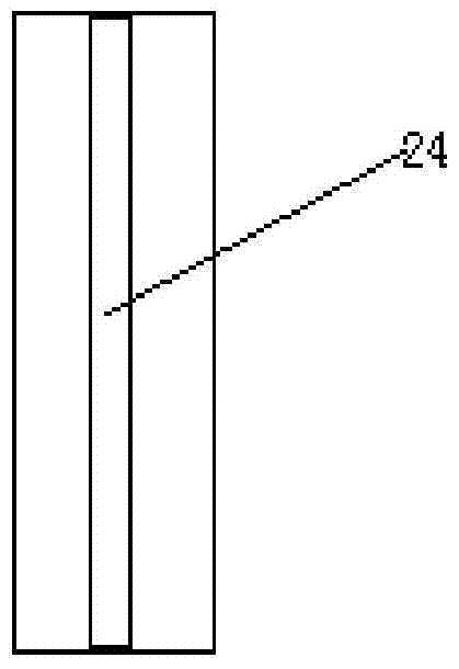
[0029] The third lifting column 23 is a cylindrical structure with an open bottom, and the outer surface of the third lifting column 23 is provided with a slider 25 that cooperates with the inner surface slide rail 24 of the outer sleeve 221 of the second lifting column 22. The lifting column 23 is provided with a rotating cylinder 231, the rotating shaft of the rotating cylinder 231 is fixed on the top of the third lifting column 23, and the bottom wall of the rotating cylinder 231 is provided with a hollow screw 223 which is connected with the second lifting column 22. Cooperate with each other.
PUM
 Abstract
Description
Claims
Application Information
 - R&D
- Intellectual Property
- Life Sciences
- Materials
- Tech Scout
- Unparalleled Data Quality
- Higher Quality Content
- 60% Fewer Hallucinations
Browse by: Latest US Patents, China's latest patents, Technical Efficacy Thesaurus, Application Domain, Technology Topic, Popular Technical Reports.
© 2025 PatSnap. All rights reserved.Legal|Privacy policy|Modern Slavery Act Transparency Statement|Sitemap|About US| Contact US: help@patsnap.com


