A detection circuit and detection method of an inductive displacement sensor

A displacement sensor and detection method technology, applied in the field of sensor detection, can solve the problems of inability to obtain the precise inductance of the sensor coil, poor environmental temperature resistance, etc., and achieve the effects of improving reliability, reducing power consumption, and reducing complexity

Active Publication Date: 2017-12-22
贵州新安航空机械有限责任公司
View PDF6 Cites 0 Cited by
  • Summary
  • Abstract
  • Description
  • Claims
  • Application Information

AI Technical Summary

Problems solved by technology

[0006] In order to solve the above-mentioned technical problems, the present invention provides a detection circuit of an inductive displacement sensor. The detection circuit of the inductive displacement sensor effectively solves the problem of the resistance of the current technology through a simple circuit structure, signal extraction and filtering strategy, and uses simple calculations. The ambient temperature capability is poor and the precise inductance of the sensor coil cannot be obtained

Method used


Image

  • A detection circuit and detection method of an inductive displacement sensor
  • A detection circuit and detection method of an inductive displacement sensor
  • A detection circuit and detection method of an inductive displacement sensor

Examples


Embodiment approach

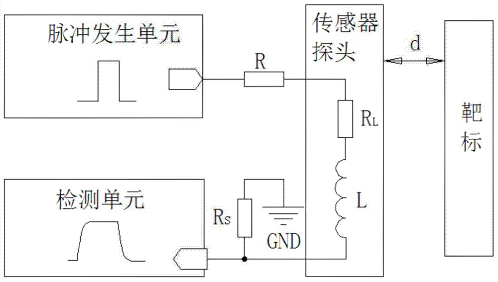
[0076] The internal resistance R of the nominal coil of the sensor at room temperature 20°C L is (12~14)Ω, when the ambient temperature changes between (-55~+70)℃, the coil internal resistance R L The distribution range of temperature drift is (10~16)Ω. When the target displacement is 4mm, the nominal inductance L of the coil is The sensor works in the close state; when the displacement of the metal target is 6mm, the change of the coil inductance relative to the inductance of 4mm is distributed in (80-120)μH, and the sensor works in the far away state.

[0077] Based on the above indicators, taking into account the emission interference and its own anti-interference ability of the present invention, the maximum excitation voltage U of the zero-state response of the coil is set m The value is 2V DC, the value of the current limiting resistor R is 47Ω, and the sampling resistor R S The value is 100Ω, and the maximum flow current of the sensor coil is about 12.5mA. The exci...


PUM


Abstract

The invention provides a detection circuit of an induction type displacement sensor. A built-in coil of the sensor is equivalent to an internal resistor RL and an inductor L in serial connection, a current limiting resistor R, the internal resistor RL, the inductor L and a sampling resistor RS are connected in series successively, and then one end of the current limiting resistor R is connected to a pulse generation unit, and one end of the sampling resistor RS is grounded; and a detection unit detects the voltage between the two ends of the sampling resistor RS or the current through the sampling resistor RS. A physical model of the displacement sensor is established, the detection circuit directly calculates the internal resistance RL of the built-in coil of the sensor in real time, the inductance L of the sensor is calculated in real time according to the internal resistance of the coil, and the work state of the sensor is determined by determining the separated internal resistance RL; and the inductor L and the internal resistance RL are calculated separately in real time in the detection process, and the real-time monitoring function (BIT) of the system can be realized needless of addition of extra resources, so that the complexity degree is greatly reduced, the reliability is improved, and the power consumption is reduced.

Description

technical field [0001] The invention relates to the technical field of sensor detection, in particular to a detection circuit of an inductive displacement sensor and a detection method thereof. Background technique [0002] The traditional displacement detection mechanism is based on mechanical micro switches, which are constrained by mechanical contacts that are easy to wear and burn; easy to fail due to liquid and dust pollution; need to be equipped with a limit mechanism; the pressing device is easy to fatigue and fail. The traditional displacement detection mechanism of the micro switch is gradually replaced by the detection technology based on the inductive displacement sensor to obtain high reliability and high precision detection of the key displacement detection mechanism. This type of technology is widely used in the industrial field, and has gradually been extended to the landing gear retractable system, wing folding system, brake system, hatch, radome and other ke...

Claims


Application Information

Patent Timeline
Patent Type & Authority Patents(China)
IPC IPC(8): G01B7/02
CPCG01B7/02
Inventor 张远杨欧阳张宏图
Owner 贵州新安航空机械有限责任公司
Why Eureka
Try Eureka