
Test apparatus for axial static rigidity of main shaft and using method thereof

A test device and static stiffness technology, which is applied in the testing of machine gears/transmission mechanisms, etc., can solve problems such as difficult testing of axial stiffness, achieve good versatility, and ensure test efficiency

Inactive Publication Date: 2016-03-09
鼎奇(天津)主轴科技有限公司
View PDF7 Cites 5 Cited by
  • Summary
  • Abstract
  • Description
  • Claims
  • Application Information

AI Technical Summary

Problems solved by technology

[0003] At present, there are many test devices about the axial static stiffness of the main shaft at home and abroad, but the existing test devices are only for a certain type of main shaft to test the axial static stiffness. The test of axial stiffness poses great difficulties

Method used


Image

  • Test apparatus for axial static rigidity of main shaft and using method thereof
  • Test apparatus for axial static rigidity of main shaft and using method thereof

Examples


Embodiment Construction

[0021] In order to further understand the invention content, characteristics and effects of the present invention, the following examples are given, and detailed descriptions are as follows in conjunction with the accompanying drawings:

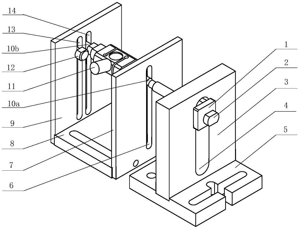
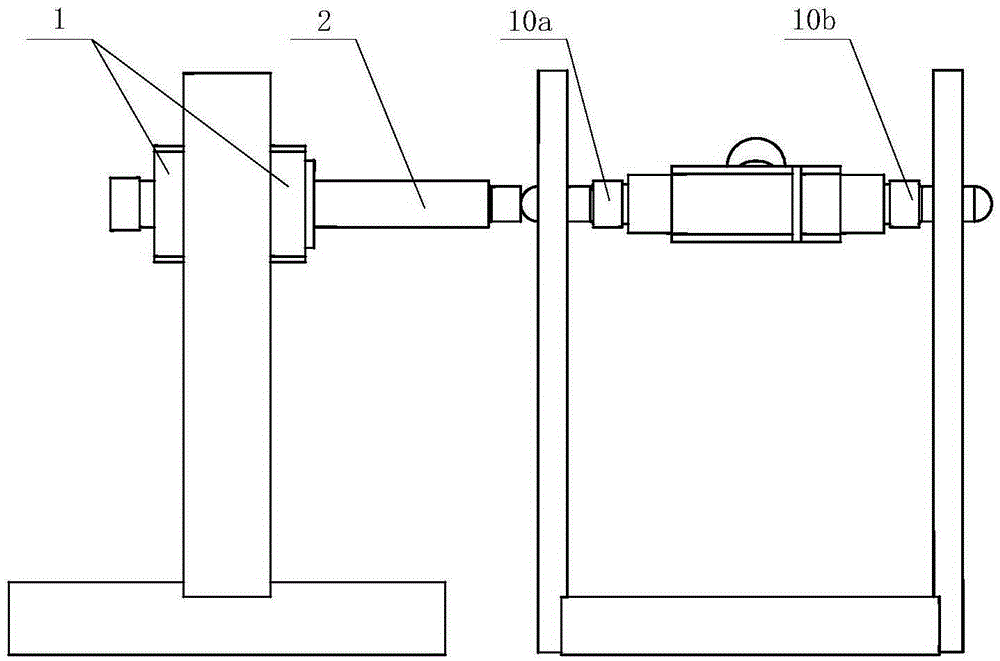
[0022] see figure 1 , a spindle axial static stiffness testing device, characterized in that it includes a locking rod bracket assembly, a sensor bracket assembly, a force sensor assembly and a displacement sensor. The locking rod bracket assembly includes a locking rod bracket bottom plate 5, a locking rod mounting plate 3, a locking rod collar 1, and a locking rod 2; the locking rod bracket bottom plate 5 is used to fix the locking rod mounting plate 3. The locking rod mounting plate 3 is provided with a locking rod mounting plate sliding groove 4, the locking rod collar 1 can move along the locking rod mounting plate sliding groove 4, and the locking rod 2 passes through The thread pair is connected with the locking rod collar 1, and the ...


PUM


Abstract

The invention discloses a test apparatus for the axial static rigidity of a main shaft. Axial load is applied to or unloaded from a main shaft through a locking rod. The locking rod is connected to a locking rod sleeve ring through a screw thread pair. The locking rod sleeve ring adjusts the horizontal height of the locking rod by sliding in a slide groove. A force sensor and a displacement sensor are adopted to measure the axial load and the axial displacement of a main shaft unit respectively. The force sensor and the displacement sensor both can slide along the slide groove so that the relative positions between the force sensor and a main shaft unit rotor and between the displacement sensor and the main shaft unit rotor are adjusted. An NI data collection card is employed to collect the axial load measured by the force sensor and the axial displacement collected by the displacement sensor, and a computer displays a static rigidity curve of the axial load-the axial displacement of the main shaft. Relative positions between the main shaft unit rotor and the force sensor, the displacement sensor, the locking rod sleeve ring and the locking rod are adjusted according to the diameter of the main shaft. In this way, the axial load and the axial displacement of main shafts different in diameter can be measured, and the test efficiency of the axial rigidity of a main shaft is guaranteed.

Description

technical field [0001] The invention relates to the field of performance testing of machine tool spindles, in particular to a testing device for axial static stiffness of a spindle and a method for using the same. Background technique [0002] The main shaft is the core functional part of the machine tool, and its performance directly affects the performance of the machine tool. The axial static stiffness of the spindle refers to the ability of the spindle unit to resist deformation under the action of axial load. Usually, the axial static stiffness of the spindle is represented by the load applied in the direction of axial displacement when the front end of the spindle rotor produces a unit axial displacement. stiffness. The axial static stiffness of the spindle is an important index to evaluate the quality of the CNC machine tool and the design of the spindle unit. It will not only affect the geometric accuracy and surface quality of the machined parts, but also the basis...

Claims


Application Information

Patent Timeline
IPC IPC(8): G01M13/02
Inventor 吕术亮
Owner 鼎奇(天津)主轴科技有限公司
Learn More