Wind farm reactive power compensation device dynamic response time detection method

A compensation device and dynamic response technology, applied in the field of detection, can solve the problems of the reactive power compensation device not moving or refusing to move, the dynamic response time measurement error, the unreasonable reactive power configuration of the wind farm, etc., achieving good versatility and improving accuracy. degree, avoid the effect of debugging workload

Active Publication Date: 2016-03-09
CHINA ELECTRIC POWER RES INST +3
View PDF8 Cites 9 Cited by
  • Summary
  • Abstract
  • Description
  • Claims
  • Application Information

AI Technical Summary

Problems solved by technology

Since 2011, there have been many large-scale wind power off-grid accidents in my country's "Three North" regions. The operation and management of reactive power compensation devices are the main reasons for the expansion of wind power accidents. slower, leading to further expansion of the fault
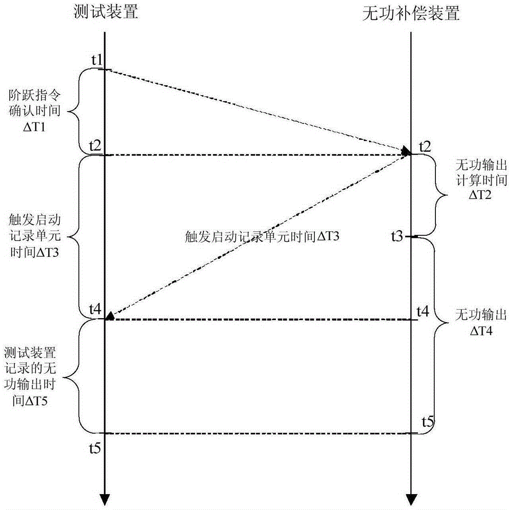
[0005] Due to the communication and execution (internal calculation and output of the reactive power compensation device) time delay in the existing wind farm reactive power compensation device dynamic response time detection method, there will be a large error in the measurement of the dynamic response time
The external voltage change is generated by switching part of the collector line or fixing the compensation equipment, the voltage change may not be obvious, and the reactive power compensation device does not move or refuses to move, which has certain limitations.
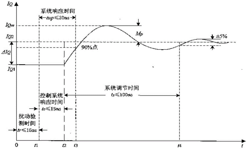
At the same time, due to the same PI parameters, the response time required for different reactive power adjustments is not the same, the response time obtained from the small voltage / reactive power disturbance measurement must be too small, and the accurate response time requires a large reactive power / voltage step to get

Method used


Image

  • Wind farm reactive power compensation device dynamic response time detection method
  • Wind farm reactive power compensation device dynamic response time detection method
  • Wind farm reactive power compensation device dynamic response time detection method

Examples


Embodiment

[0062] Example: Some large-scale wind farms have a rated capacity of more than 100MW, and there may be multiple sets of reactive power compensation devices, and the reactive power compensation devices may be provided by different manufacturers, resulting in different monitoring systems. If there are multiple sets of reactive power compensation devices under the same main transformer in the wind farm, and there is a coordinated control mechanism among the reactive power compensation devices, the method of testing the dynamic response time of one set of reactive power compensation devices should be followed, but a second set of reactive power compensation devices needs to be added. Compensation device outlet current detection. If there is no coordinated control mechanism among multiple sets of reactive power compensation devices, the reactive power compensation devices can be tested one by one according to the method of testing the dynamic response time of one set of reactive pow...


PUM


Abstract

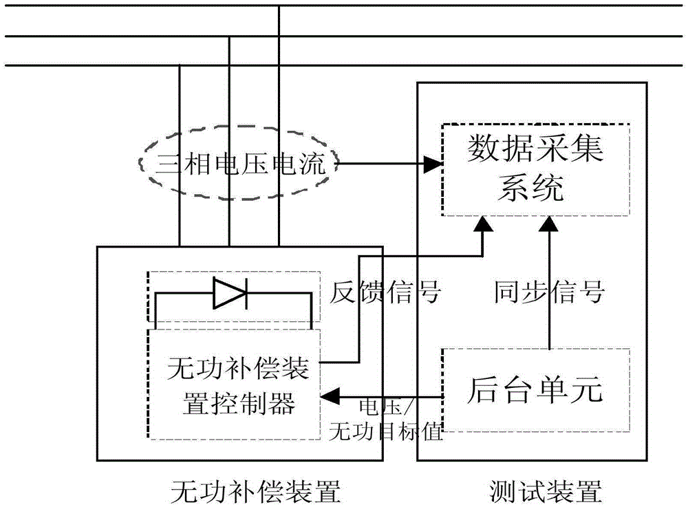
The present invention provides a wind farm reactive power compensation device dynamic response time detection method. The method comprises a step of analyzing a reactive power compensation device dynamic response time requirement, a step of determining the time of sending a synchronization signal to a data acquisition system by a testing device background unit, the time of sending a voltage / reactive power target value to a reactive power compensation device and the time of outputting a feedback signal to the data acquisition system by the reactive power compensation device, a step of obtaining a reactive power compensation device dynamic response time, and a step of sending the synchronization signal and the feedback signal to the data acquisition system, calling the data acquisition system to obtain a reactive power compensation device accurate dynamic response time and verifying whether the accurate dynamic response time meets a standard requirement or not. The method is simple to operate and easy to realize, and the method can be automatically completed by a testing system without human intervention, in the condition of satisfying a wind farm safety requirement, the accurate measurement of the reactive power compensation device dynamic response time is realized.

Description

technical field [0001] The invention relates to a detection method, in particular to a dynamic response time detection method of a wind farm reactive power compensation device. Background technique [0002] Nowadays, wind power presents a trend of rapid development, and the installed capacity is getting bigger and bigger, and the proportion of wind power in the power grid is also rising accordingly. Since 2011, there have been many large-scale wind power off-grid accidents in my country's "Three North" regions. The operation and management of reactive power compensation devices are the main reasons for the expansion of wind power accidents. Slower, leading to further expansion of the fault. In order to improve the operational reliability of reactive power compensation devices (SVC, STATCOM) in wind farms, meet the requirements for voltage regulation and stability of the power grid, and strengthen the safety and stability of wind farms and power grids, the enterprise standard...

Claims


Application Information

Patent Timeline
Patent Type & Authority Applications(China)
IPC IPC(8): G01R31/00
CPCG01R31/00
Inventor 张金平晏青樊熠王瑞明常喜强郭小龙张彦军
Owner CHINA ELECTRIC POWER RES INST
Why Eureka
Try Eureka