Virtual wave beam forming method based on coprime arrays

A virtual beam and array technology, applied in radio wave measurement systems, instruments, etc., can solve problems such as fading, disordered output beams, and main lobe degradation

Inactive Publication Date: 2016-03-09
CHENGDU UNIVERSITY OF TECHNOLOGY
View PDF4 Cites 15 Cited by
  • Summary
  • Abstract
  • Description
  • Claims
  • Application Information

AI Technical Summary

Problems solved by technology

However, in this method, part of the grating lobes are retained and degenerated into side lobes when the sub-beams are multiplied and fused, causing obvious side-lobe interference. In addition, when there are multiple signal sources in the space, the grating lobes of the signal sources in the sub-beams will alias When the main lobe enters, the main lobe of the sub-beam is di...

Method used


Image

  • Virtual wave beam forming method based on coprime arrays
  • Virtual wave beam forming method based on coprime arrays
  • Virtual wave beam forming method based on coprime arrays

Examples


Embodiment 1

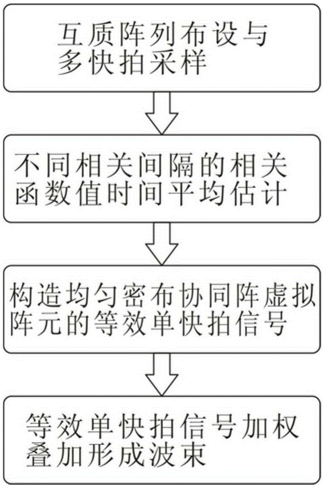
[0058] Embodiment 1: see Figure 1 to Figure 12 , a virtual beamforming method based on a coprime array, comprising the following steps:

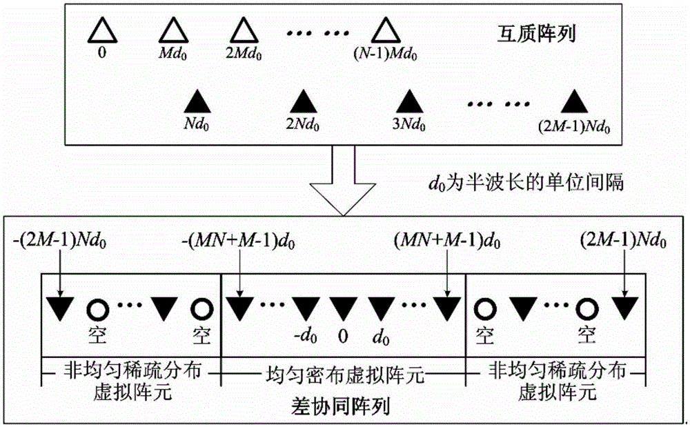
[0059] 1) Arrange multiple array elements to form a coprime array, and perform multi-snapshot sampling on the incident signals of multiple non-correlated signal sources in different spatial directions; the specific method is: arrange N+2M-1 array elements to include two A coprime array of uniform sparse subarrays, the array element position is:

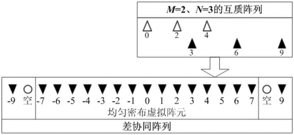
[0060] x={Mnd 0 ,0≤n≤N-1}U{Nmd 0 ,1≤m≤2M-1}(1) In formula (1), d 0 is the unit interval of half wavelength, when the working frequency is f 0 time d 0 =λ / 2=c / 2f 0 ; In this embodiment, we set M=2, N=3, half-wavelength unit interval d 0 =1.

[0061] When the power is L, The L mutually uncorrelated signal sources along their respective directions θ 1 ,θ 2 ,L,θ L is incident to the coprime array, then the received signal vector at the kth snapshot sampling moment is expressed as:

[00...


PUM


Abstract

The invention discloses a virtual wave beam forming method based on coprime arrays. The method comprises the steps of: firstly, arranging a plurality of array elements to form the coprime arrays, and carrying out multi-snapshot sampling on incident signals of a plurality of non-relevant signal sources in different spatial directions; carrying out time averaging estimation on correlation function values different in correlation space; then based on corresponding relations between correlation spaces and coprime array difference cooperation array virtual array element positions, extracting the correlation function values having the continuous correlation spaces, and constructing equivalent single-snapshot signals of virtual array elements uniformly distributed in difference cooperation arrays; and finally, according to the position distribution of the uniformly distributed virtual array elements, designing weight vectors, and carrying out weighted superposition on the equivalent single-snapshot signals so as to obtain output wave beams. According to the invention, the characteristic that most virtual array elements are uniformly distributed in the difference cooperation arrays of the coprime arrays is utilized to solve the problems of an existing sparse subarray wave beam multiple multiplication method that sidelobe interference exists and the method is not suitable for a plurality of signal sources, the wave beam signal to noise ratio is effectively increased, and the noise resistance is improved.

Description

technical field [0001] The invention belongs to the technical field of array beamforming, and relates to a virtual beamforming method based on a coprime array. Background technique [0002] The coprime array is a new type of non-uniform sparse array proposed in 2010. It consists of two uniform sparse sub-arrays with a coprime relationship between array elements. Compared with traditional non-uniform arrays such as minimum redundancy matrix and nested array Sparse arrays and coprime arrays have outstanding advantages such as simple layout design of array elements and little influence of mutual coupling of array elements. [0003] Array signal processing has been widely used in radar, sonar, communication, seismic exploration and other fields. Its two main research directions are direction of arrival estimation and beamforming. The coprime array was first applied to the direction of arrival estimation of the space signal source, and the dimensionality of the correlation matri...

Claims


Application Information

Patent Timeline
IPC IPC(8): G01S7/28
CPCG01S7/2813
Inventor 贾勇钟晓玲郭勇周瑞陈俊杰吉江涛
Owner CHENGDU UNIVERSITY OF TECHNOLOGY
Why Eureka
Try Eureka