Laser source device and laser projection device

A laser light source and laser technology, applied in projection devices, optics, instruments, etc., can solve the problems of large volume of optical path space, large number of optical components, and inability to meet miniaturization, so as to simplify and compress optical paths, reduce optical path components, and meet miniaturization requirements. the effect of

Inactive Publication Date: 2016-03-09
HISENSE
View PDF3 Cites 19 Cited by
  • Summary
  • Abstract
  • Description
  • Claims
  • Application Information

AI Technical Summary

Problems solved by technology

[0009] It can be seen from the above that in the prior art, on the one hand, the laser needs to pass through a beam shaping optical path composed of multiple lenses to form a smaller spot to reach the fluorescent wheel for fluorescence excitation, and at least a collimating lens group needs to be set on the back of the fluorescent wheel (for figure 1 The reflective fluorescent wheel in the center needs to be set on b

Method used


Image

  • Laser source device and laser projection device
  • Laser source device and laser projection device
  • Laser source device and laser projection device

Examples


Embodiment 1

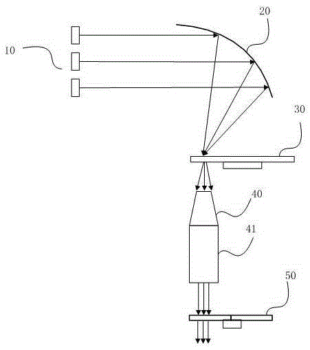
[0044] Embodiment 1 of the present invention provides a solution of a laser light source device, which will be described in detail below.

[0045] figure 2 It is a schematic diagram of the structure of the laser light source device, such as figure 2 As shown, the device can include: a laser 10, a beam converging component 20 and a wavelength conversion component 30, a light cone component 40, and a uniform light component 41; wherein: the laser 10 can be one or more groups, for emitting at least one A laser beam of several colors; a wavelength conversion device 30 for being excited to produce at least one color of fluorescence; a beam converging part 20 for converging the laser light emitted by the laser 10 to the wavelength conversion part 30 to excite the wavelength conversion part 30 The fluorescent conversion material emits fluorescence; the light beam converging part 20 has a reflective curved surface, and the laser 10 and the wavelength conversion part 30 are all loca...

Embodiment 2

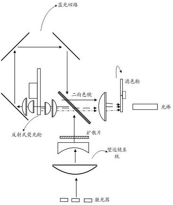
[0083] Embodiment 2 of the present invention provides yet another laser light source device, such as Figure 7 As shown, it includes a blue laser 11, a light-combining component 13, a red laser 12, a reflective cup or a reflective bowl 20, a diffuser 21, a transmissive fluorescent wheel 30, a light cone component 40, a uniform light component 41, and a filter component 50 .

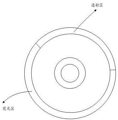
[0084] The specific structure and materials of the transmissive fluorescent wheel and how the blue laser light and the red laser light emitted by the blue laser 11 and the red laser 12 are transmitted through the transmissive fluorescent wheel 30 will be described in detail.

[0085] In implementation, the laser includes a blue laser and a red laser, and the fluorescent area is one or a combination of the following phosphor areas: green phosphor area, yellow phosphor area;

[0086] In practice, if the laser includes a blue laser 11 and a red laser 12, the phosphor area is one of the following phosphor ar...

Embodiment 3

[0091] Embodiment 3 of the present invention provides yet another laser light source device, such as Figure 8 shown. Compared with the light source structure in Embodiment 1, a second reflective cup or reflective bowl component 60 is also provided on the back of the wavelength conversion component 30, or after the light output port, and before the light cone component 40. The reason for this arrangement is that : Due to the different sizes of the DMD chip in the optical-mechanical system behind the light source device, the received light spot size is different, and the light cone part and the light rod are used in combination, and the outgoing light spot of the light rod can be regarded as consistent with the light spot size of the exit end of the light cone part , if the spot area required by the DMD chip is small, it is necessary to further compress the divergence angle of the beam or compress the area of ​​the spot to meet the requirement. Therefore, preferably, before th...


PUM


Abstract

The invention discloses a laser source device. The laser source device comprises a laser device emitting lasers of at least one color, a wavelength conversion part used for being excited to generate fluorescence of at least one color, a light beam convergence part, a light cone part and a light uniformizing part. The light beam convergence part is used for converging the lasers emitted by the laser device to the wavelength conversion part. Use of multiple lenses in the light beam compression process is reduced. The light beam convergence part comprises a light reflection hook face. The laser device and the wavelength conversion part are both located on the same side of the light reflection hook face. The space of the light path along which the lasers are emitted to the wavelength conversion device is compressed. The light cone part is used for conducting divergence angle compression on combined light beams of the lasers of at least one color and fluorescence of at least one color, use of collimation and convergent lenses is reduced, compression light routes of the combined light of the lasers and the fluorescence are simplified. The light uniformizing part is used for outputting light beams output by the light cone part in a uniformized mode. By means of the laser source device, light path elements can be reduced, the space of the light path is compressed, the structure is simplified, and miniaturization requirements are met.

Description

technical field [0001] The invention relates to the technical field of optical equipment, in particular to a laser light source device and laser projection equipment. Background technique [0002] With the demand for miniaturization and portability of laser projection equipment, it is necessary to provide a miniaturized laser projection equipment, especially a miniaturized laser light source device. [0003] figure 1 It is a structural diagram of the laser light source device, such as figure 1 As shown, the laser light source device in the prior art includes a laser, and the blue laser is shown in the example; the fluorescent wheel is coated with green phosphor and yellow phosphor (or red phosphor), and the front of the phosphor wheel and There are collimating lens groups on the back; since the spot area of ​​the blue laser is larger after exiting the laser, and the spot required for excitation on the fluorescent wheel is smaller, it is necessary to perform beam shaping to...

Claims


Application Information

Patent Timeline
IPC IPC(8): G03B21/20
CPCG03B21/204G03B21/2066
Inventor 王强刘显荣田有良李巍
Owner HISENSE
Why Eureka
Try Eureka