Broadband dielectric resonator antenna based on planar monopole patch excitation

A dielectric resonator, monopole technology, applied in the direction of the connection of the antenna grounding switch structure, the structure of the radiating element, etc., can solve the problems of limited development and application, high ohmic loss of metal conductors, and large antenna geometry, and achieve flexible design. Degree of freedom, reduced profile, and low dielectric loss

Inactive Publication Date: 2016-03-09
CNGC INST NO 206 OF CHINA ARMS IND GRP
View PDF2 Cites 19 Cited by
  • Summary
  • Abstract
  • Description
  • Claims
  • Application Information

AI Technical Summary

Problems solved by technology

However, the microstrip patch antenna has two key technical bottlenecks, the high ohmic loss of the metal conductor in the high frequency band

Method used


Image

  • Broadband dielectric resonator antenna based on planar monopole patch excitation
  • Broadband dielectric resonator antenna based on planar monopole patch excitation
  • Broadband dielectric resonator antenna based on planar monopole patch excitation

Examples


Embodiment Construction

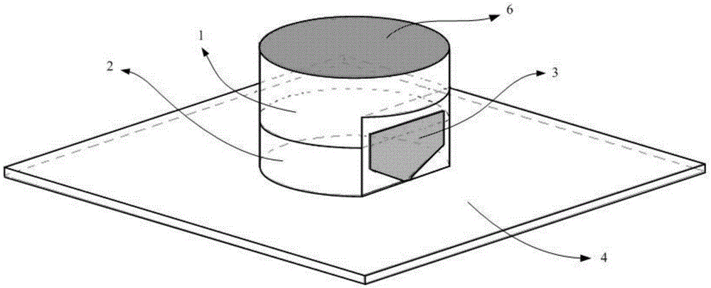
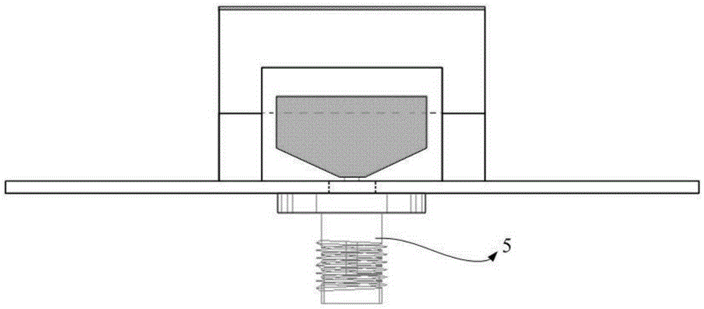
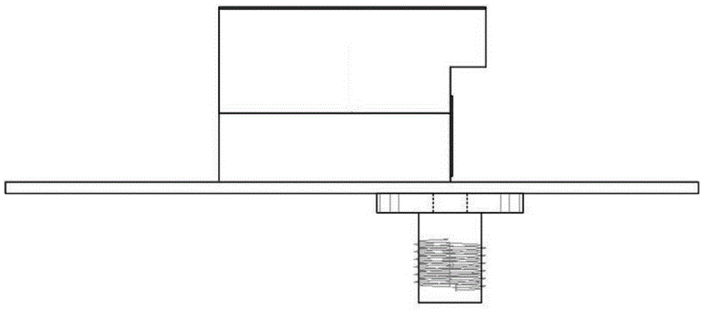
[0022] Now in conjunction with embodiment, accompanying drawing, the present invention will be further described:

[0023] The broadband dielectric resonator antenna based on planar monopole patch excitation mainly includes dielectric resonator, support foam material, planar monopole patch, metal floor and SMA connector from the structural point of view. The dielectric resonator is used as the radiation body of the antenna, and its structural shape is a cylinder with gaps. The selected material is RogersTMM10i microwave ceramic substrate with a dielectric constant εr = 9.8. The metal cladding is loaded on the top surface of the dielectric resonator cylinder, which can be regarded as a perfect electric conductor (PEC) interface, which is beneficial to the realization of broadband performance. Since the dielectric constant of the dielectric resonator is much larger than that of air, its interface with air can be regarded as a perfect magnetic conductor (PMC) interface. Therefor...


PUM


Abstract

The invention relates to a broadband dielectric resonator antenna based on planar monopole patch excitation, comprising a cylindrical dielectric resonator with a gap, a support foam material, a planar monopole patch, a square metal floor and a feeding SMA connector. The radiation body of the antenna is the cylindrical dielectric resonator with a gap, the top surface is loaded with a metal coating, and the inverted trapezoidal planar monopole patch is adopted for excitation. The dielectric resonator is placed on the metal floor. The foam material of which the dielectric constant is close to 1.0 is used to support the dielectric resonator. The antenna has the advantages of compact and reliable structure, low cost, low processing difficulty and high radiation efficiency, can meet the performance requirement of the working band from 3GHz to 6.5GHz, and is very suitable for a C-band broadband wireless communication system.

Description

technical field [0001] The invention relates to a broadband dielectric resonator antenna based on planar monopole patch excitation, which can be used as a terminal antenna of a C-band broadband wireless communication system, and belongs to the technical field of wireless communication system antennas. Background technique [0002] With the rapid development of wireless communication systems, high-performance requirements such as miniaturization, broadband, and high efficiency are put forward for the terminal antenna as its key component. In this technical field, the microstrip patch antenna has been deeply researched and widely used because of its low profile, easy integration, and low cost. However, the microstrip patch antenna has two key technical bottlenecks, the high ohmic loss of the high-frequency metal conductor and the large geometric size of the low-frequency antenna, which limits its further development and application to a certain extent. In recent years, dielec...

Claims


Application Information

Patent Timeline
IPC IPC(8): H01Q1/38H01Q1/50H01Q1/36
CPCH01Q1/38H01Q1/36H01Q1/50
Inventor 杨亚兵李绪平赵迎超郑慕昭石俊峰
Owner CNGC INST NO 206 OF CHINA ARMS IND GRP
Why Eureka
Try Eureka