Checking method and system of high-cycle cutting machine configuration scheme

A configuration scheme and cutting machine technology, applied in the direction of circuit devices, AC network circuits, electrical components, etc., can solve problems such as excess power, inability to take stable control measures for the system, and failure to meet the safety and stability standards of the power grid.

Active Publication Date: 2016-03-09
ELECTRIC POWER RESEARCH INSTITUTE, CHINA SOUTHERN POWER GRID CO LTD +1
View PDF4 Cites 15 Cited by
  • Summary
  • Abstract
  • Description
  • Claims
  • Application Information

AI Technical Summary

Problems solved by technology

[0004] (1) When the outgoing DC is blocked, the frequency of the power grid at the sending end increases due to the instantaneous power surplus after the fault. For single-circuit large-capacity DC, unipolar blocking occurs, according to the "Guidelines for Safety and Stability of Power Systems (DL755-2001) 》, the system cannot take stable control measures, and the sending-end power grid may cause the first round of high-frequency cut-off due to the frequency increase, which does not meet the safety and stability standards of the power grid's ability to withstand large disturbances;
[0005] (2) Considering the more serious situation, when the outgoing DC multiple circuits are blocked at the same time and the stability control device refuses to operate, the power grid at the sending end is seriously overpowered. If the duration is long, it may cause the overspeed protection of the thermal power unit to operate disorderly;
[0006] (3) During the process of multiple DC commutation failures in the sending-end grid caused by the failure of the receiving-end grid, the frequency of the sending-end grid may cause the high-cycle switching device to operate. When the fault disappears and the DC power gradually recovers, the sending-end grid will resume The low frequency load shedding device will operate due to the frequency reduction due to power shortage

Method used


Image

  • Checking method and system of high-cycle cutting machine configuration scheme
  • Checking method and system of high-cycle cutting machine configuration scheme
  • Checking method and system of high-cycle cutting machine configuration scheme

Examples


Embodiment Construction

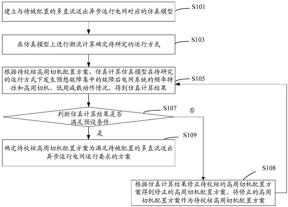
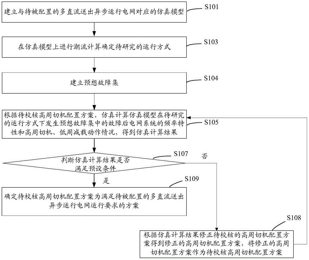
[0041] Such as figure 1 As shown, the verification method of the configuration scheme of the high-cycle cut-off machine for the asynchronous operation grid with multiple DC transmissions includes:

[0042] S101: Establish a simulation model corresponding to the to-be-configured multi-direct current sending asynchronous operation grid.

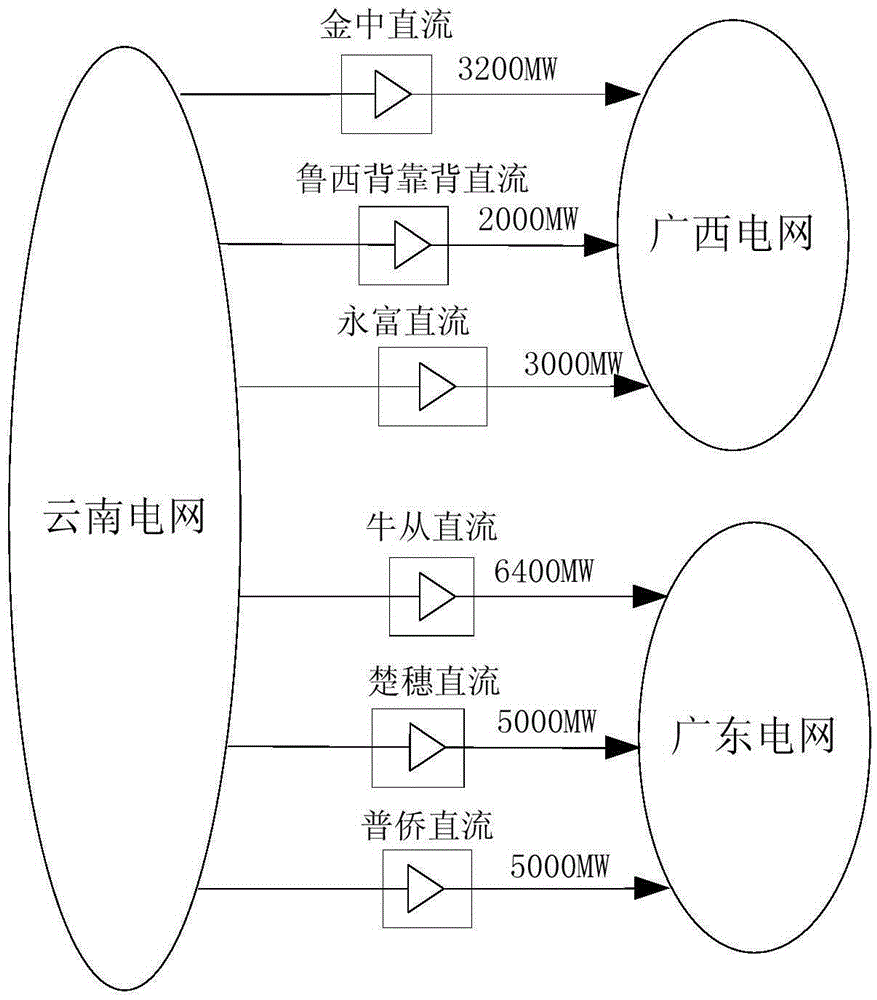
[0043] The asynchronous operation grid with multi-DC transmission means that the grid in this area has no AC connection line with the main grid, and is only connected to the main grid through multiple DC circuits.

[0044] The simulation model refers to the topology used to simulate the operation of the power grid to be configured. The simulation model includes the DC detailed model considering the DC control system, and the unit speed governor model considering the dead zone and the adjustment coefficient. Among them, the dead zone and the adjustment coefficient in the governor model of the unit are simulated many times to obtain parameters ...


PUM


Abstract

The present invention provides a checking method and system of a high-cycle cutting machine configuration scheme of a multi-DC feed asynchronous operation grid. According to the checking method, through using simulation model simulation, the condition of a grid system after a fault in a forecast fault set happens is calculated to obtain a simulation calculation result, the forecast fault set comprises a traditional grid external feed section breaking fault and also comprises the influence of a non-synchronous operation grid fault on a researched grid frequency, and the high-cycle cutting machine configuration scheme can be checked and corrected so as to obtain a scheme which satisfies a configured multi-DC feed asynchronous operation grid operation requirement. According to the checking method of the high-cycle cutting machine configuration scheme of the multi-DC feed asynchronous operation grid, the factor consideration is comprehensive, the operability is strong, the practical value is high, and the market prospect is good.

Description

technical field [0001] The invention relates to the field of electric power system control, in particular to a method and system for checking the configuration of high-frequency cut-off machines in a power grid with multi-direct current transmission and asynchronous operation. Background technique [0002] With the increasing power of DC transmission, the risk of safe and stable operation of the system brought about by the parallel operation of AC and DC is becoming more and more prominent. In order to avoid large-scale power outages when multiple faults occur in the power grid, the grid planning gradually considers the implementation of asynchronous interconnection grids, that is, there is no AC connection line between the two AC systems, but only through the DC line, and the generator rotors in the two systems do not need to be connected. keep in sync. Although the asynchronous interconnected grid has greatly improved the stability of the system's transient power angle, t...

Claims


Application Information

Patent Timeline
Patent Type & Authority Applications(China)
IPC IPC(8): H02J3/00
CPCH02J3/00H02J2203/20
Inventor 吴小珊柳勇军徐光虎林峰
Owner ELECTRIC POWER RESEARCH INSTITUTE, CHINA SOUTHERN POWER GRID CO LTD
Why Eureka
Try Eureka