Fluid power sound source excitation method of piezoelectric generator

A fluid power and generator technology, applied in the direction of generators/motors, piezoelectric effect/electrostrictive or magnetostrictive motors, electrical components, etc., can solve problems such as large volume, poor anti-interference, complex structure, etc.

Active Publication Date: 2016-03-09
NANJING UNIV OF SCI & TECH
View PDF6 Cites 24 Cited by
  • Summary
  • Abstract
  • Description
  • Claims
  • Application Information

AI Technical Summary

Problems solved by technology

This invention relies on a linearly moving piston mechanism to adjust the airflow and the cantilever beam piezoelectric array. Similarly, there are problems of low system strength, poor anti-interference, complex structure, and large volume.

Method used


Image

  • Fluid power sound source excitation method of piezoelectric generator
  • Fluid power sound source excitation method of piezoelectric generator
  • Fluid power sound source excitation method of piezoelectric generator

Examples


Embodiment 1

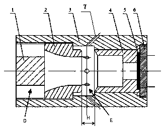
[0032] according to Figure 1 to Figure 5 As shown, the device of the present invention is mainly composed of a vibrating structure comprising an air inlet D, a nozzle 2, and a sound tube 4, and a piezoelectric sheet 5 fixed at the bottom of the sound tube 4; wherein, one end of the casing 3 forms an air inlet with the plug 1 D, the inner hole of the nozzle 2 is a Widowshinski structure; the other end is arranged in sequence with a sound tube 4 and a piezoelectric sheet 5, which is fixedly connected to the outer shell 3 through the outer end cover plate 6, and the piezoelectric sheet 5 is tightly pressed on the sound tube 4 end; there is a cavity E between the nozzle 2 and the sound tube 4.

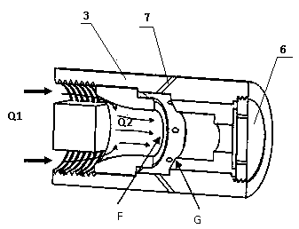
[0033] Such as image 3 As shown, the air inlet D is a narrow side gap formed by the casing 3 and the plug 1, the plug 1 is an external thread structure, and two symmetrical planes are milled on the 1 / 2 radius of the cylindrical basic body to form a structure.

[0034] Such as Figure ...


PUM


Abstract

The invention provides a fluid power sound source excitation method of a piezoelectric generator. By means of change characteristics generated by air flow after the air flow flows through a pipeline and the characteristic that sound waves cause structure vibration when spreading in a cavity and a pipe hole, a novel air flow induced sound piezoelectric power generation forced vibration device free of movable parts is provided. The device is provided with a non-linear vibration mechanical system capable of mechanically and automatically adjusting air flow to excite a fluid power sound source, can meet the requirement of self-power-supply of application systems in various fields such as automobiles, unmanned vehicles, weapon application systems, aerospace and aviation systems, robots and city or community illumination, fully uses clean renewable energy sources and has important theoretical value and engineering mentoring meaning.

Description

technical field [0001] The invention provides a piezoelectric generator fluid dynamic sound source excitation method, relates to a fluid dynamic sound source using air flow to induce sound waves, and a device for exciting a piezoelectric transducer to output electric energy, and belongs to the technical field of air flow piezoelectric power generation. Background technique [0002] The key to vibrating piezoelectric generators lies in efficient electromechanical energy conversion and high power harvesting circuits. Various high-power acquisition circuits, whether using standard interface circuits or switch-based synchronous circuits, have relatively mature theories and designs. Various low-loss energy acquisition circuits have been developed, and their structures are basically the same. The key to electromechanical transducers lies in high-performance piezoelectric materials or piezoelectric composite materials, and their preparation processes, which belong to the field of m...

Claims


Application Information

Patent Timeline
Patent Type & Authority Applications(China)
IPC IPC(8): H02N2/18
CPCH02N2/185
Inventor 陈荷娟邹华杰孙加存蔡建余聂伟荣赖长缨杨坚张健谭菊琴吴朝阳姜节波
Owner NANJING UNIV OF SCI & TECH
Why Eureka
Try Eureka