
RFID-based phase shift keying signal demodulation method

A technology of signal demodulation and phase shift keying, which is applied in the field of signal demodulation, can solve the problems of reducing the anti-noise performance of signal demodulation and reducing the correlation performance of spreading codes, so as to improve anti-noise performance, improve correlation performance, solve The effect of simple tuning method

Active Publication Date: 2016-03-09
CHONGQING SOUTHWEST INTEGRATED CIRCUIT DESIGN
View PDF3 Cites 7 Cited by
  • Summary
  • Abstract
  • Description
  • Claims
  • Application Information

AI Technical Summary

Problems solved by technology

Due to the state of 0 value in the dot product and difference product under QPSK / DQPSK modulation, the performance related to the spreading code is reduced, and the anti-noise performance of signal demodulation is also reduced

Method used


Image

  • RFID-based phase shift keying signal demodulation method
  • RFID-based phase shift keying signal demodulation method
  • RFID-based phase shift keying signal demodulation method

Examples


Embodiment Construction

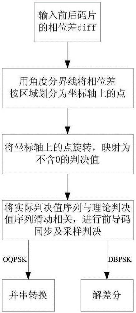
[0050] see figure 1 , the phase-shift keying signal demodulation method based on RFID, comprises the steps:

[0051] Step 1, input the phase difference of the front and back chips;

[0052] Step 2, set the angle dividing line, and use the angle dividing line to divide the phase difference into points on the coordinate axis according to the area;

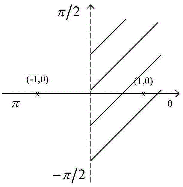
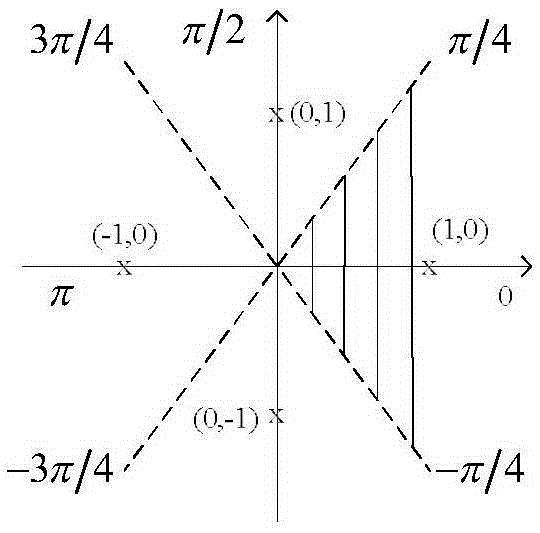
[0053] Due to the influence of the transmission carrier, the 0-frequency signal obtained by the receiving end is not a square wave such as +1 and -1 during encoding, but a sine wave with phase delay, so the phase difference is not the same as the theoretical phase difference. Only the cases of -π / 2, 0, π / 2, and π are continuously changing curves, so it is necessary to use a dividing line to divide the phase difference into points on the coordinate axis.

[0054] Specifically, proceed as follows:

[0055] Such as figure 2 As shown, for the DBPSK modulation signal, take nπ / 2 (n=±1) as the angle dividing line, divide the phase diff...


PUM


Abstract

The present invention discloses an RFID-based phase shift keying signal demodulation method. The method is characterized by comprising a step of inputting the phase difference of front and back chips, a step of setting an angle boundary and using the angle boundary to divide the phase difference as points on a coordinate axis according to areas, a step of rotating the points on the coordinate axis according to the same direction for a fixed angle, and then mapping the points on the coordinate axis as a judgment value without 0, a step of preamble synchronization, a step of sampling judgment, and a step of output conversion. According to the method, the angle boundary is used to judge the phase difference of the front and back chips according to the areas, then a judgment result is rotated, the judgment value which is not equal to 0 is mapped and generated, and the relevant performance of a spreading code is raised so as to improve the anti-noise performance of PSK signal demodulation. The demodulation method of a phase shift keying signal is simple and unique and can be widely used in a radio frequency identification system.

Description

Technical field: [0001] The invention relates to a signal demodulation method, in particular to an RFID-based phase shift keying signal demodulation method. technical background: [0002] The radio frequency identification (RFID) system, which works in ultra-high frequency (UHF) and microwave frequency bands, has the advantages of long operating distance and fast reading and writing speed compared with the widely used mid-low frequency RFID system, and has become the current international technology and product development hotspot. However, RFID technology in the UHF band and microwave band is still in its infancy in China. Although there are many international RFID standards in the world, in order to meet the needs of domestic RFID technology level and industrial scale, and national information security considerations, China promulgated the national standard GB / T28925-2012 "Information Technology Radio Frequency Identification 2.45GHz" in 2012 Air Interface Protocol". Th...

Claims


Application Information

Patent Timeline
IPC IPC(8): H04L27/233H04B1/7075G06K7/10
CPCG06K7/10009H04B1/70752H04L27/2331
Inventor 田翠翠陈刚舒海翔范麟万天才刘永光徐骅李明剑
Owner CHONGQING SOUTHWEST INTEGRATED CIRCUIT DESIGN
Learn More