MIMO radar orthogonal waveform design method and system
What is AI technical title?
AI technical title is built by PatSnap AI team. It summarizes the technical point description of the patent document.
A technology of orthogonal waveforms and design methods, applied in radio wave measurement systems, mechanical equipment, instruments, etc., can solve the problems of mutual interference between different systems and the deterioration of radar system performance, and achieve optimized related performance, good optimization effect, and low calculation. The effect of complexity
Pending Publication Date: 2022-08-02
NAT UNIV OF DEFENSE TECH
View PDF0 Cites 0 Cited by
Summary
Abstract
Description
Claims
Application Information
AI Technical Summary
This helps you quickly interpret patents by identifying the three key elements:
Problems solved by technology
Method used
Benefits of technology
Problems solved by technology
[0004] When designing orthogonal waveforms in existing methods, most of them establish a cost function based on the auto / cross-correlation performance of the waveforms. Although the orthogonality between waveforms can be improved, the interaction between different systems will still occur in complex electromagnetic environments. disturb
The existence of interference signals in actual work often makes the radar system performance worse
Method used
Image
Click on the blue label to locate the original text in one second.
Reading with bidirectional positioning of images and text.
Examples
no. 1 example
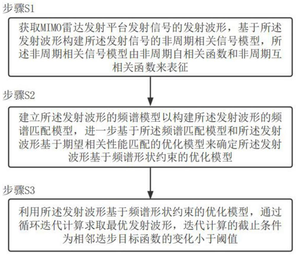
[0217] 1. Build the aperiodic correlation signal model of the MIMO radar transmit waveform, the specific aperiodic autocorrelation function A l,k and the cross-correlation function C p,q,k The expression is as follows:
[0218]
[0219]
[0220] Among them, l,p,q=1,2,...,L, p≠q, k=0,1,...,N-1.
[0223] Among them, δ is the shock function, which defines the matrix J p,q,k as follows:
[0224]
[0225] Among them, Z p,q Indicates that the (p, q)th element is 1 and the remaining elements are 0 L×L-dimensional matrix, represents the Kronecker product.
[0226] Based on the above definition, the compact expression of the aperiodic correlation function of the MIMO radar transmit waveform can be given as:
[0227] A l,k =s H J l,l,k s
[0228] C p,q,k =s H J p,q,k s
[0229] Among them, s=[s 1 ,s 2 ,...,s L ] H .
[0230] 2. Build the spectrum model of the MIMO radar transmit waveform:
[0231] define mat...
no. 2 example
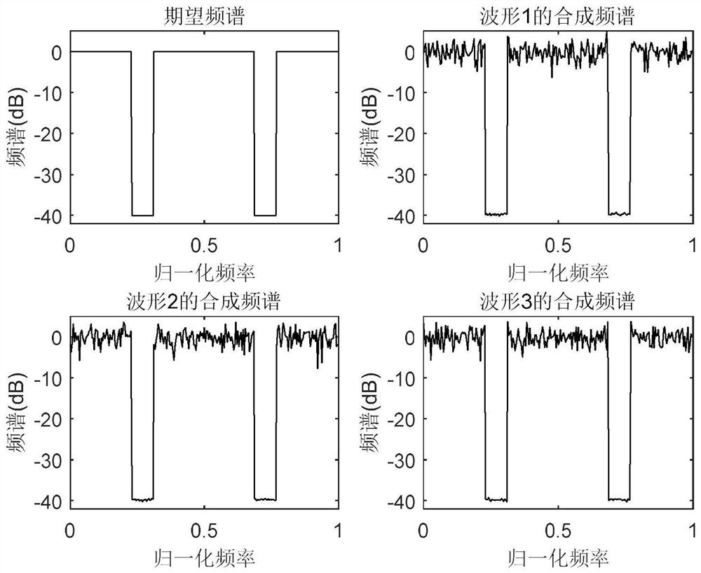
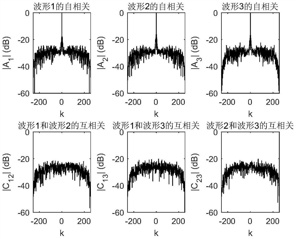
[0286] Second Embodiment (Simulation of First Embodiment)
[0287] Simulation conditions: The number of array elements of the MIMO radar is L=3, and the encoding length of the transmitted waveform of each array element is N=256. When the change of the objective function value of adjacent iteration steps is less than 0.1, the iteration is stopped.
[0288] figure 2 The correlation function of the waveform obtained by the simulation of the second embodiment according to the optimization of the first embodiment of the present invention is given; as figure 2 As shown, the correlated sidelobe level of the optimized MIMO radar waveform is very low, which provides a good basis for matched filtering between different waveforms.
[0289] image 3 The frequency spectrum of the waveform obtained by the simulation of the second embodiment according to the optimization of the first embodiment of the present invention is given; as image 3 As shown in the figure, the spectrum of the o...
PUM
Abstract
The invention provides an MIMOradar orthogonal waveform design method and system. According to the method, the orthogonal waveform of the MIMOradar is designed by constraining the frequency spectrum shape, the MIMOradar is a multiple-input-multiple-output radar, and the method comprises the steps of obtaining a transmitting waveform of a transmitting signal of a transmitting platform of the MIMO radar, constructing a non-periodic correlation signal model of the transmitting signal based on the transmitting waveform, and constructing a non-periodic correlation signal model of the transmitting signal based on the non-periodic correlation signal model; the aperiodic correlation signal model is represented by an aperiodic autocorrelation function and an aperiodic cross-correlation function; establishing a frequency spectrum model of the transmitted waveform to construct a frequency spectrum matching model of the transmitted waveform, and further determining a frequency spectrum shape constraint-based optimization model of the transmitted waveform based on the frequency spectrum matching model and an expected correlation performance matching-based optimization model of the transmitted waveform; the optimal transmitted waveform is obtained through loop iterative calculation by means of an optimization model of the transmitted waveform based on the spectrum shape constraint, and the cut-off condition of the iterative calculation is that the change of the adjacent step target function is smaller than a threshold value.
Description
technical field [0001] The invention belongs to the field of radar systems and radar signal processing, and in particular relates to a method and system for designing a quadrature waveform of a MIMO radar. Background technique [0002] As a new system radar, MIMO radar has received extensive attention from many scholars since it was proposed. Compared with traditional phased array radars, MIMO radars can transmit arbitrary waveforms, have higher degrees of freedom, and have very superior performance in target detection and parameter estimation. According to the different antenna configuration, it can be divided into statistical MIMO radar and coherent MIMO radar. Statistical MIMO radar transceiver array elements have a large configuration spacing and can observe the target from different directions, so it has good spatial gain, structural gain and polarization gain, and can effectively overcome the target RCS scintillation effect. The target echo of coherent MIMO radar can...
Claims
Application Information
Patent Timeline
Application Date:The date an application was filed.
Publication Date:The date a patent or application was officially published.
First Publication Date:The earliest publication date of a patent with the same application number.
Issue Date:Publication date of the patent grant document.
PCT Entry Date:The Entry date of PCT National Phase.
Estimated Expiry Date:The statutory expiry date of a patent right according to the Patent Law, and it is the longest term of protection that the patent right can achieve without the termination of the patent right due to other reasons(Term extension factor has been taken into account ).
Invalid Date:Actual expiry date is based on effective date or publication date of legal transaction data of invalid patent.

