Thin film drying method, thin film drying device, and device including thin film

A drying method and drying device technology, which are applied in the manufacturing of semiconductor/solid-state devices, electrical components, circuits, etc., can solve the problems of affecting device performance and poor compactness of material film layers, and achieve the effect of improving related performance and compactness.

Pending Publication Date: 2020-12-22
NANJING TECH CORP LTD
View PDF0 Cites 0 Cited by
  • Summary
  • Abstract
  • Description
  • Claims
  • Application Information

AI Technical Summary

Problems solved by technology

[0003] However, after drying with the existing drying method or drying device, the compactness of the material film laye

Method used


Image

  • Thin film drying method, thin film drying device, and device including thin film
  • Thin film drying method, thin film drying device, and device including thin film

Examples


Embodiment 1

[0067] (1) Preparation of semi-finished products of QLED devices: On 30*30mm ITO glass, spin-coat PEDOT with a thickness of 40nm and poly(9-vinylcarbazole) (PVK) with a thickness of 30nm in sequence and dry them; print with DMP2831 desktop The equipment prints green quantum dot ink on the dried PVK surface under the condition of 30 μm drop interval, the concentration of quantum dots in the quantum dot ink is 1wt%, the solvent in the quantum dot ink includes nonane and octanol The volume ratio is nonane:octanol=7.5:2.5, and the thickness of the wet film after printing is about 50nm.

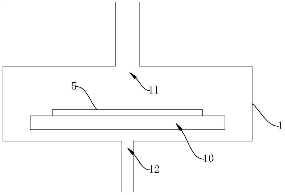
[0068] (2) Dry the semi-finished QLED device above: place the printed green quantum dot ink substrate at room temperature T 1 , Atmospheric pressure P 1 (P 1 = 1 bar, T 1 =25°C) in the cavity, after the cavity is sealed, nitrogen gas is introduced to increase the pressure in the cavity to P 2 , P 2 =100bar, then turn on the heating to raise the substrate temperature to T 2 ,T 2 =100°C; then...

Embodiment 2

[0071] (1) The method for preparing the QLED device semi-finished product is the same as the step (1) of Example 1.

[0072] (2) Dry the above-mentioned QLED device semi-finished products: place the substrate printed with green quantum dot ink at room temperature T 1 , Atmospheric pressure P 1 (P 1 = 1 bar, T 1 = 25°C), after the cavity is sealed, nitrogen and octanol saturated vapor at 25°C are introduced to increase the pressure in the cavity to P 2 , P 2 =100bar, then turn on the heating to raise the substrate temperature to T 2 ,T 2 =100°C; then gradually reduce the pressure in the cavity to normal pressure P at a rate of 0.1bar / s 1 after 10 -5 The decompression rate of bar / s reduces the chamber pressure to P 3 , P 3 =10 -4 bar, after maintaining the air pressure for 30 minutes, turn off the heating, inject nitrogen gas to restore the cavity pressure to normal pressure, and continue to inject nitrogen gas to lower the cavity temperature. After it returns to norma...

Embodiment 3

[0075] (1) The method for preparing the QLED device semi-finished product is the same as the step (1) of Example 1.

[0076] (2) Dry the above-mentioned QLED device semi-finished products: place the substrate printed with green quantum dot ink at room temperature T 1 , Atmospheric pressure P 1 (P 1 = 1 bar, T 1 =25°C) in the cavity, after the cavity is sealed, nitrogen gas is introduced to increase the pressure in the cavity to P 2 , P 2 =100bar, then turn on the heating to raise the substrate temperature to T 2 ,T 2 =100°C; then gradually reduce the pressure in the cavity to normal pressure P at a rate of 0.1bar / s 1 after 10 -5 The decompression rate of bar / s reduces the chamber pressure to P 3 , P 3 =10 -4 bar, then increase the substrate temperature to T 3 ,T 3 =150°C, after maintaining the air pressure for 30 minutes, turn off the heating, inject nitrogen gas to restore the cavity pressure to normal pressure, and continue to inject nitrogen gas to lower the cav...


PUM

PropertyMeasurementUnit
Thicknessaaaaaaaaaa
Thicknessaaaaaaaaaa

Abstract

The invention discloses a thin film drying method, a thin film drying device and a device comprising a thin film, the thin film drying method comprises the following steps: S1, a substrate with a wetfilm on the surface is placed in a container of the drying device, the initial air pressure in the container is P1, and the initial temperature in the container is T1; S2, the interior of the container is pressurized, and then the temperature in the container is increased, so that the air pressure in the container is increased to P2, and the temperature is increased to T2; and S3, the air pressurein the container is gradually reduced to P3 from P2, P3 is smaller than P1, and the air pressure in the container is kept for the time t under P3. According to the invention, the purpose of controlling the solvent volatilization rate is achieved by pressurizing and then decompressing, the solvent residual quantity in the wet film is the highest in the initial stage of drying, the volatilization rate of the solvent is limited by pressurizing at the moment, and the solvent is promoted to gradually volatilize in the middle stage of drying in a gradual decompressing manner. According to the invention, the film layer is uniformly dried, and the film layer with good compactness and flatness can be obtained.

Description

technical field [0001] The present invention relates to a drying method and a drying device, in particular to a film drying method, a film drying device and a device including a film. Background technique [0002] At present, in the wet process of devices (especially in the field of optoelectronic devices), it is necessary to rely on vacuum drying technology to obtain dry films. Under high vacuum, the solvent can be volatilized at a lower temperature, thereby avoiding damage to the device by high temperature. [0003] However, after drying with existing drying methods or drying devices, the material film layer is less dense, and sometimes defects similar to "craters" appear on the surface, thereby affecting the performance of the device. Contents of the invention [0004] In order to overcome the deficiencies of the prior art, the object of the present invention is to provide a film drying method, which can improve the compactness and uniformity of the film by drying the ...

Claims


Application Information

Patent Timeline
IPC IPC(8): H01L21/67
CPCH01L21/67034
Inventor 顾辛艳
Owner NANJING TECH CORP LTD
Why Eureka
Try Eureka