Radiating treatment structure

A heat sink and heat dissipation material technology, applied in the direction of modification through conduction heat transfer, cooling/ventilation/heating modification, etc., can solve the problems affecting the production progress and high cost, and achieve the effect of optimizing the shell temperature

Inactive Publication Date: 2016-03-09
SALCOMP SHENZHEN CO LTD
View PDF5 Cites 5 Cited by
  • Summary
  • Abstract
  • Description
  • Claims
  • Application Information

AI Technical Summary

Problems solved by technology

The potting glue treatment needs to consider the impact on other aspects after the process is completed. It is necessary to use a combined abrasive tool to divide the potting area, resulting in a relatively high cost of the product. The product needs to be hardened before it can be assembled, and it also affects the production schedule.

Method used


Image

  • Radiating treatment structure

Examples


specific Embodiment approach 1

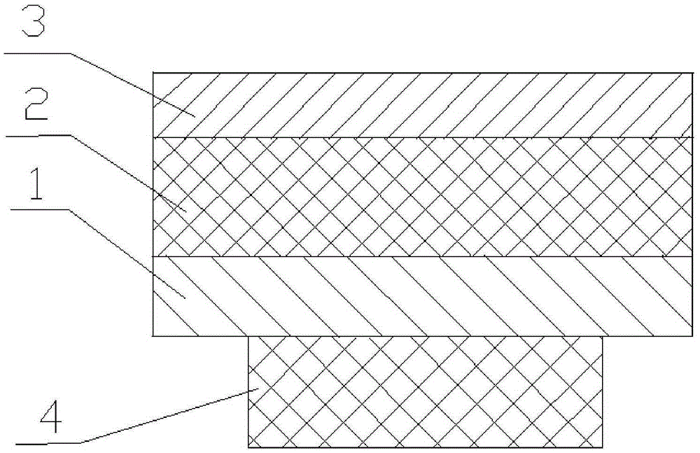
[0024] A heat dissipation treatment structure as shown in the attached drawing includes a heat sink that is close to the heat source 4 of the product, the heat sink is a "sandwich" structure, and the heat dissipation in the horizontal direction and the heat insulation in the vertical direction are adopted to reduce the heat source of the product. The temperature of each point on the outer surface of the product is determined, and the heat source of the product is subjected to an isothermal cooling treatment to optimize the heat treatment of the product.

[0025] The bottom layer in the shape of a "sandwich" structure is the first heat dissipation material 1 that is close to the product heat source 4, the surface layer is the second heat dissipation material 3, the middle layer between the bottom layer and the surface layer is the heat insulation material 2, the bottom layer, the middle layer and the surface layer in turn. Connected by lamination, the first heat dissipation mate...

specific Embodiment approach 2

[0029] A heat dissipation processing structure as shown in the accompanying drawings includes a heat sink that is close to the product heat source 4, and the heat sink is a "sandwich" structure, which is basically the same as the first embodiment. The difference is:

[0030] The bottom layer, the middle layer and the surface layer are connected with glue in turn;

[0031] The first heat dissipation material 1 is a copper sheet with a thermal conductivity of 100 W / m·K and a thickness of 0.05 mm.

[0032] The heat insulating material 2 is a silica aerogel having a thermal conductivity of 0.024 W / m·K and a thickness of 0.6 mm.

[0033] The second heat dissipation material 3 is an aluminum sheet with a thermal conductivity of 100 W / m·K and a thickness of 1.00 mm.

[0034] Embodiment 2 Compared with Embodiment 1, the temperature of the product shell is about 2°C higher, and the heat dissipation treatment effect is slightly worse.


PUM


Abstract

A radiating treatment structure is disclosed. The radiating treatment structure comprises a radiating fin tightly clung to a product heating source; the radiating treatment structure is characterized in that the radiating fin is in a sandwich-like structure; a mode of heat radiation in a horizontal direction and heat insulation in a perpendicular direction is adopted; a first radiating material tightly clung to the product heating source is arranged at the bottom layer; a second radiating material is arranged on the surface layer; a thermal insulating material is arranged in the intermediate layer between the bottom layer and the bottom layer; the thermal insulating material is used for preventing the peak temperature from zooming up in order to reduce the peak temperature of the product to the maximum; and the second radiating material is used for performing heat dissipation and temperature equilibrium treatment again on the heat that is already subjected to the thermal insulation treatment so as to enable the temperature to be averaged to the maximum, reduce the peak temperature and achieve the optimized temperature equilibrium treatment. The radiating treatment structure can reduce the peak temperature of the product to the maximum and achieve a temperature equilibrium effect on the product shell. The radiating treatment structure is particularly applicable to optimization treatment on the shell temperature of small-sized products.

Description

technical field [0001] The present invention relates to heat dissipation, in particular to a heat dissipation processing structure. Background technique [0002] The temperature above the heat source of the product is the highest point temperature, and it is also the highest point temperature after it is reflected on the product shell. The existing cooling treatments for the highest temperature point temperature include heat sink treatment, heat dissipation glue treatment, potting glue treatment, and large-scale products. Cooling fans, water cooling, etc. are used. There are many heat dissipation treatment methods for miniaturized products that cannot be applied, and only ordinary heat sink and potting glue treatment methods can be used. Heat sinks can homogenize the heat somewhat, but if the heat source is close to the product case, hot spots can still form on the outer surface of the product, even with heat sinks. The potting glue treatment needs to consider the impact o...

Claims


Application Information

Patent Timeline
Patent Type & Authority Applications(China)
IPC IPC(8): H05K7/20
CPCH05K7/2039
Inventor 刘棠良王腾月
Owner SALCOMP SHENZHEN CO LTD
Why Eureka
Try Eureka