Heat uniform distribution and dissipation structure and heat uniform distribution and dissipation process for portable electronic equipment

A technology for electronic equipment and heat dissipation. It is applied to the structural parts of electrical equipment, electrical components, and decoration through conduction and heat transfer. It can solve problems such as poor user experience, insignificant heat dissipation effect, and slow crash.

Pending Publication Date: 2017-05-31
M VICTORY SPECIFIC MATERIAL
View PDF6 Cites 7 Cited by
  • Summary
  • Abstract
  • Description
  • Claims
  • Application Information

AI Technical Summary

Problems solved by technology

[0002] At present, the handheld devices on the market will experience partial overheating after long-term use. This phenomenon not only brings consumers a bad experience of excessively high tactile temperature, but also is caused by the core components of the mobile phone such as the high-performance CPU running. The heat cannot be transferred out in an effective way, so that the command cycle of the mobile phone is limited, and even the phenomenon of too slow crash occurs from time to time. Since the appearance of the current handheld device requires too thin thickness, there is no space reserved for the traditional heat transfer method. heat convection (using fans to obtain convection), so only heat conduction and heat radiation can be applied. At present, most handheld devices on the market use high thermal conductivity materials such as graphite sheets and copper foils attached near the heat source. It achieves the purpose of heat dissipation, but the industry often confuses the concept of uniform heat dissipation. It is not clear what it means, and it is used casually. Judging from the large-screen mobile phones of Meizu, Xiaomi, Huawei and other brands on the market, there is no significant heat dissipation effect, and the local temperature is still high. , consumers often complain
[0003] In addition, the concept of uniform heat dissipation in the prior art is confused, and the heat dissipation effect is not obvious. The heat emitted by the heat source of the handheld device cannot be evenly distributed in the entire cavity, and the temperature of the core and the body continues to rise, causing the body to become hot or crash. Can only passively use software to reduce core efficiency, causing bad user experience to consumers

Method used


Image

  • Heat uniform distribution and dissipation structure and heat uniform distribution and dissipation process for portable electronic equipment
  • Heat uniform distribution and dissipation structure and heat uniform distribution and dissipation process for portable electronic equipment
  • Heat uniform distribution and dissipation structure and heat uniform distribution and dissipation process for portable electronic equipment

Examples


Embodiment 1

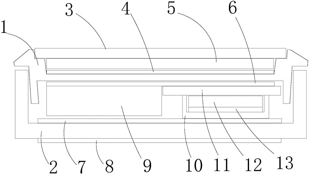
[0027] Such as figure 1 As shown, the outer surface of the front shell 1 is pasted with a first heat equalizing layer 4 , the first heat equalizing layer is made of silver material, and a display screen 5 and a touch screen 3 are pasted on the front of the first heat equalizing layer 4 .

[0028] The inner surface of the front shell 1 is pasted with a second heat equalizing layer 6, and the rear portion of the second heat equalizing layer 6 is pasted side by side with a battery 9 and a circuit board 11. The inside of the chip is a chip 12, and one side of the chip 12 is pasted on the circuit board 11.

[0029] A first heat dissipation layer 7 is pasted on the inner side of the rear case 2 , and a second heat dissipation layer 8 is pasted on the outer side of the rear case.

[0030] On the inner side and / or outer side of the front shell 1 above the circuit board 11, use paste, smear, electroplating, and spray related heat-conducting materials to evenly distribute the heat emit...

Embodiment 2

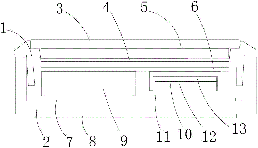
[0033] Such as figure 2 As shown, the outer surface of the front shell 1 is pasted with a first heat equalizing layer 4 , the first heat equalizing layer is made of silver material, and a display screen 5 and a touch screen 3 are pasted on the front of the first heat equalizing layer 4 .

[0034] A first heat dissipation layer 7 is pasted on the inner side of the rear case 2 , and a second heat dissipation layer 8 is pasted on the outer side of the rear case.

[0035] The inner surface of the front shell 1 is pasted with a second heat equalizing layer 6, and the rear portion of the second heat equalizing layer 6 is pasted side by side with a battery 9 and a shielding cover 10. The inside of the shielding case 10 is a chip 12, and one side of the chip 12 is pasted on the on the circuit board 11. The other side of the circuit board 11 is pasted on the first heat dissipation layer 7 .

[0036] On the inner side and / or outer side of the front shell 1 above the circuit board 11,...


PUM


Abstract

The invention provides a heat uniform distribution and dissipation structure and a heat uniform distribution and dissipation process for portable electronic equipment. The heat uniform distribution and dissipation structure comprises a front shell and a rear shell. The rear shell is fastened at the rear of the front shell, a display screen and a touch screen are arranged at the front of the front shell, and electronic components are arranged inside a shell comprising the front shell and the rear shell. The heat uniform distribution and dissipation structure is characterized by further comprising heat uniform distribution layers and heat dissipation layers, the heat uniform distribution layers are arranged at the front of the portable electronic equipment, the heat dissipation layers are arranged at the rear of the portable electronic equipment, and a composite membrane is arranged on each electronic component. The heat uniform distribution and dissipation structure and the heat uniform distribution and dissipation process have the advantages that heat diffused by heat sources of the handheld equipment can be uniformly dispersed in integral cavities (by the heat uniform distribution layers), heat exchange can be carried out on the external (and the heat dissipation layers), accordingly, core temperatures can be definitely reduced, the problem of heating of machine bodies or breakdown can be solved, the performance of the electronic equipment can be relatively sufficiently played, and consumers can have excellent man-machine experience.

Description

technical field [0001] The invention relates to the field of heat dissipation structure technology, in particular to a heat dissipation structure and technology for portable electronic equipment. Background technique [0002] At present, the handheld devices on the market will experience partial overheating after long-term use. This phenomenon not only brings consumers a bad experience of excessively high tactile temperature, but also is caused by the core components of the mobile phone such as the high-performance CPU running. The heat cannot be transferred out in an effective way, so that the command cycle of the mobile phone is limited, and even the phenomenon of too slow crash occurs from time to time. Since the appearance of the current handheld device requires too thin thickness, there is no space reserved for the traditional heat transfer method. heat convection (using fans to obtain convection), so only heat conduction and heat radiation can be applied. At present, m...

Claims


Application Information

Patent Timeline
Patent Type & Authority Applications(China)
IPC IPC(8): H05K7/20
CPCH05K7/2039H05K7/20481H05K7/205
Inventor 陈宥嘉杨翔宇
Owner M VICTORY SPECIFIC MATERIAL
Why Eureka
Try Eureka