Sound transducer array having broadband receiving elements

A technology of receiving elements and sending elements, which is applied in the field of sensor systems, can solve problems such as reducing system sensitivity, and achieve the effect of increasing the range of action and improving sensitivity

Active Publication Date: 2016-03-09
ROBERT BOSCH GMBH
View PDF5 Cites 0 Cited by
  • Summary
  • Abstract
  • Description
  • Claims
  • Application Information

AI Technical Summary

Problems solved by technology

but this reduces the sensitivity of the overall system

Method used


Image

  • Sound transducer array having broadband receiving elements
  • Sound transducer array having broadband receiving elements
  • Sound transducer array having broadband receiving elements

Examples


Embodiment Construction

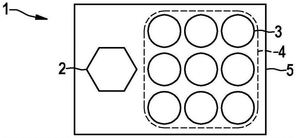
[0026] Figure 1a A sensor device 1 for detecting surroundings of a vehicle is shown, which has a transmitting element 2 and a plurality of receiving elements 3 . The receiving elements 3 are arranged geometrically in an array 4 . Both the transmitting element 2 and the receiving element 3 are located on the same carrier structure 5 . In this case, the sensor device 1 is not limited to a transmitter element 2 .

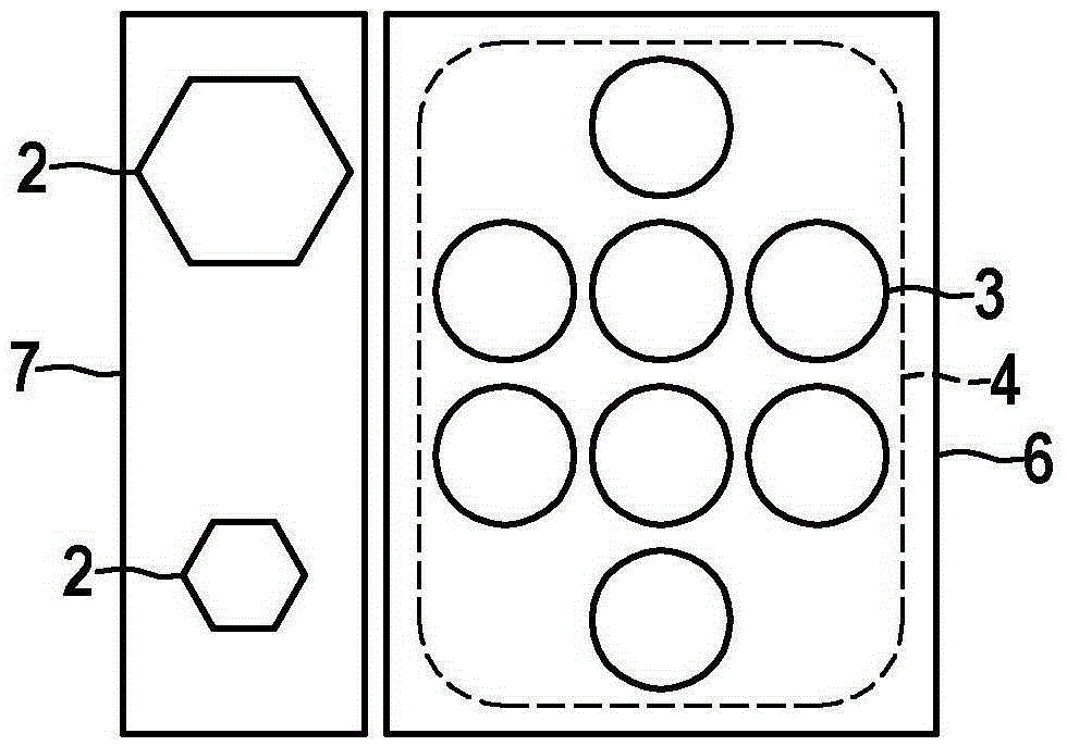
[0027] exist Figure 1b Another sensor arrangement for detecting the surroundings of a vehicle is shown in . The sensor device comprises two transmitting elements 2 arranged in a line with a vertical offset relative to one another and having different geometrical dimensions. Furthermore, the sensor device has an array 4 with a plurality of receiving elements 3 .

[0028] In a non-illustrated exemplary embodiment, two transmitting elements 2 can have a mutual horizontal offset.

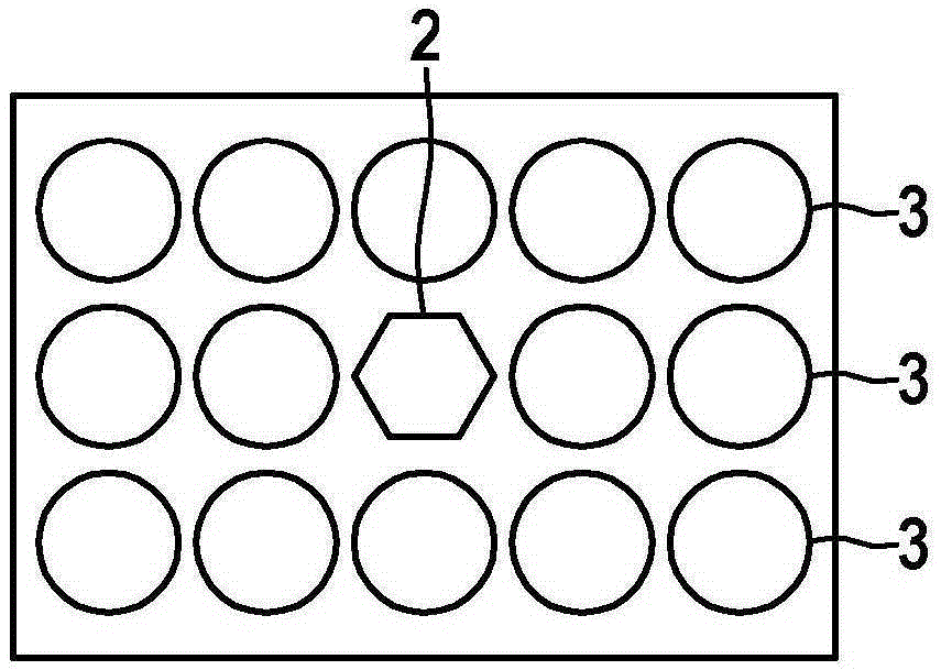
[0029] In an exemplary embodiment not shown, there can be several transmission elemen...


PUM


Abstract

The invention relates to a vehicle sensor system for locating objects situated in the surroundings of the vehicle, said sensor system having at least one transmitting element, wherein the at least one transmitting element has a bandwidth at a transmission frequency and is designed to transmit ultrasound signals at the transmission frequency, and a receiving element functionally separated from the at least one transmitting element. The at least one receiving element has a bandwidth at a center frequency and is designed to receive ultrasound signals that are reflected by the objects surrounding the vehicle. The sensor system is characterized in that the bandwidth of the receiving element is greater than the bandwidth of the transmitting element.

Description

technical field [0001] The invention relates to a sensor system for locating objects of a vehicle, having at least one transmitting element and at least one receiving element, wherein the receiving element and the transmitting element are functionally separated from one another. Background technique [0002] An ultrasonic sensor system for locating objects in the vehicle surroundings is formed from a plurality of individual ultrasonic transducers arranged in a distributed manner on the vehicle. The ultrasonic transducer assumes both the function of the ultrasonic transmitter and the function of the ultrasonic receiver. The ultrasonic transducer is realized as a so-called curved transducer element. The design of the curved transducer element is achieved in such a way that the oscillation mode for generating and detecting the ultrasound signal corresponds to the center frequency of the ultrasound system. The frequency shift between the transmitted ultrasonic signal and the r...

Claims


Application Information

Patent Timeline
Patent Type & Authority Applications(China)
IPC IPC(8): G01S15/93G01S7/54G01S15/00G01S15/87G01S15/931
CPCG01S15/931G01S7/521G01S7/54G01S13/0209G01S15/003G01S15/582G01S15/586G01S15/876
Inventor M·利布勒尔A·格拉赫
Owner ROBERT BOSCH GMBH
Why Eureka
Try Eureka