
Power drive mechanism of multi-freedom-degree mechanical arm

A power-driven, robotic arm technology, applied in manipulators, program-controlled manipulators, manufacturing tools, etc., can solve the problems of uneconomical, increased equipment weight, and high manufacturing costs, and achieve the effect of simplifying the structure and achieving good practical effects.

Active Publication Date: 2016-03-16
安徽修武工业技术有限公司
View PDF8 Cites 2 Cited by
  • Summary
  • Abstract
  • Description
  • Claims
  • Application Information

AI Technical Summary

Problems solved by technology

[0002] At present, most of the driving methods of the manipulator use servo motor drive, steel wire drive, hydraulic drive, etc., and a small part use artificial muscle drive; among them, the servo motor drive and steel wire drive need to use the same number of drive motors as the number of degrees of freedom of the manipulator, resulting in a more complex mechanism. Complicated, of course, the cost is the lowest; hydraulic drive requires strong power to pressurize the hydraulic oil, which will increase the weight of the equipment and require higher technical maturity, so the cost is higher. For artificial muscle drive, although the drive The method is advanced, but the manufacturing cost is currently the highest, which makes it uneconomical to use artificial muscles to drive ordinary robotic arms.

Method used


Image

  • Power drive mechanism of multi-freedom-degree mechanical arm
  • Power drive mechanism of multi-freedom-degree mechanical arm
  • Power drive mechanism of multi-freedom-degree mechanical arm

Examples


Embodiment Construction

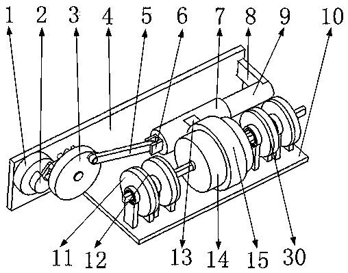
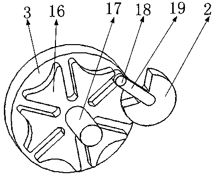
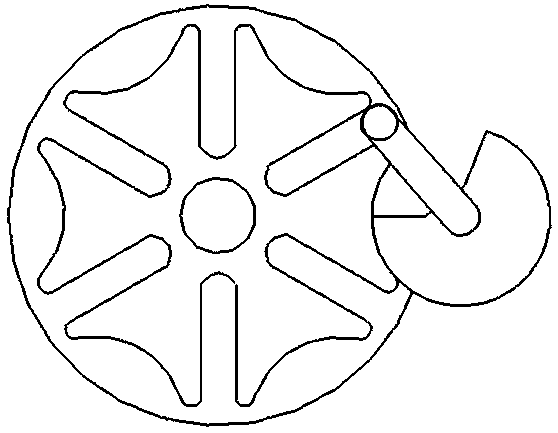
[0036] like figure 1As shown, it includes reciprocating drive motor 1, dial 2, sheave support wheel 3, first support plate 4, rocker 5, first lug 6, sliding sleeve 7, guide rail support 8, guide rail 9, second support Plate 10, gear drive motor support 13, gear drive motor 14, gear drive motor fixing ring 15, gear drive mechanism 30, sheave 16, sheave rotating shaft 17, cylindrical pin 18, rotating arm 19, gear drive motor clamping shaft 28, Conductive block 29, gear drive motor rotating shaft 31, wherein as figure 1 As shown, the reciprocating drive motor 1 is installed on the first support plate 4, as Figure 4 As shown, the dial 2 is installed on the rotating shaft of the reciprocating drive motor 1, as figure 2 , 3 As shown, one end of the rotating arm 19 is installed at the center of the dial 2 and the rotating arm 19 points to the radial direction of the dial 2, the sheave 16 is installed on the sheave support wheel 3, and the sheave 16 is installed on the first shea...


PUM


Abstract

The invention belongs to the technical field of mechanical arm drive, and particularly relates to a power drive mechanism of a multi-freedom-degree mechanical arm. The power drive mechanism comprises a reciprocating drive motor, a rocker, a gear drive motor, a grooved wheel, a gear drive motor clamping shaft, an electric conduction block and the like. Clearance rotation of the reciprocating motor is achieved through cooperation of a rotating arm and the grooved wheel. The gear drive motor is driven by a rocker mechanism to do clearance reciprocating movement. A plurality of gear drive mechanisms are arranged on the gear drive motor clamping shaft side by side, the drive motor corresponds to only one gear drive mechanism during each period of clearance standing time of the drive motor, the rotation angles of drive gears are controlled by changing the torque and the rotation angle of the drive motor, and a certain freedom degree of the mechanical arm is controlled in a driving manner. Under the condition that one drive motor is used, the aim of controlling the rotation angles of the multiple gears is achieved through a clearance mechanism and the rocker mechanism, and the mechanical arm with multiple freedom degrees is then controlled; and the structure of the mechanical arm is greatly simplified because the number of drive motors is greatly decreased, and therefore a good practical effect is achieved.

Description

Technical field [0001] The invention belongs to the technical field of mechanical arm driving, and in particular relates to a power driving mechanism of a multi-degree-of-freedom mechanical arm. Background technique [0002] At present, most of the driving methods of manipulators use servo motor drive, wire drive, hydraulic drive, etc., and a few use artificial muscle drive; among them, servo motor drive and wire drive need to use the same number of drive motors as the number of degrees of freedom of the manipulator, resulting in a relatively high mechanism. Complex, of course, the cost is the lowest; hydraulic drive requires strong power to pressurize the hydraulic oil, which will increase the weight of the equipment and require higher technical maturity, so the cost is higher. For artificial muscle drive, although the drive The method is advanced, but the manufacturing cost is currently the highest, which makes it very uneconomical for general robotic arms to use artificia...

Claims


Application Information

Patent Timeline
IPC IPC(8): B25J9/12
CPCB25J9/102B25J9/126
Inventor 陈杰
Owner 安徽修武工业技术有限公司
Learn More