Self-locking abduction-adduction mechanism for thumb of dexterous robot hand

A hand thumb and robot technology, applied in the field of self-locking abduction and adduction mechanism, can solve the problems such as difficult to realize the movement function of human hand to palm, and achieve the effects of miniaturization design and heat dissipation, easy maintenance and high integration

Inactive Publication Date: 2016-03-16
HARBIN INST OF TECH
View PDF6 Cites 3 Cited by
  • Summary
  • Abstract
  • Description
  • Claims
  • Application Information

AI Technical Summary

Problems solved by technology

[0003] The purpose of the present invention is to solve the problem that the existing robot dexterous hand thumb mechanism is difficult to r

Method used


Image

  • Self-locking abduction-adduction mechanism for thumb of dexterous robot hand
  • Self-locking abduction-adduction mechanism for thumb of dexterous robot hand
  • Self-locking abduction-adduction mechanism for thumb of dexterous robot hand

Examples


Embodiment approach 1

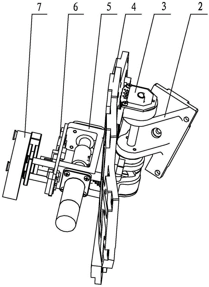
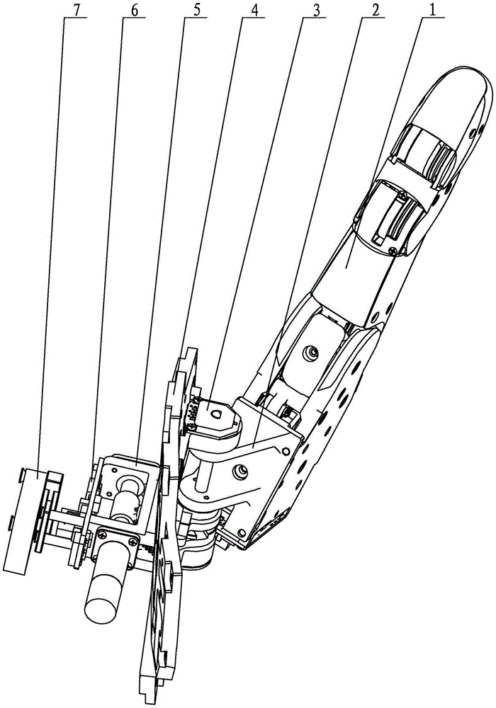
[0022] Embodiment 1: Combining Figure 1 to Figure 12 Describe this embodiment in detail, this embodiment comprises thumb support seat 2, worm gear and worm transmission mechanism 5, absolute position sensor 3, drive circuit board 6 and palm board frame 4, and described worm gear and worm transmission mechanism 5 is arranged on the palm board frame 4 On one side, a driving circuit board 6 is arranged on the worm and gear transmission mechanism 5, and the thumb support seat 2 is located on the other side of the palm plate frame 4, and an absolute position sensor 3 is arranged on the palm plate frame 4;

[0023] The worm and gear transmission mechanism 5 includes a motor 5-1, a reducer 5-2, a worm 5-9, a worm wheel 5-7, a worm shaft 5-17, an integral box 5-5 and an auxiliary base 5-20, The auxiliary base 5-20 is arranged side by side with the integral box body 5-5 and both are fixedly installed on the palm board frame 4, and the motor 5-1, the reducer 5-2 and the worm 5-9 are ar...

specific Embodiment approach 2

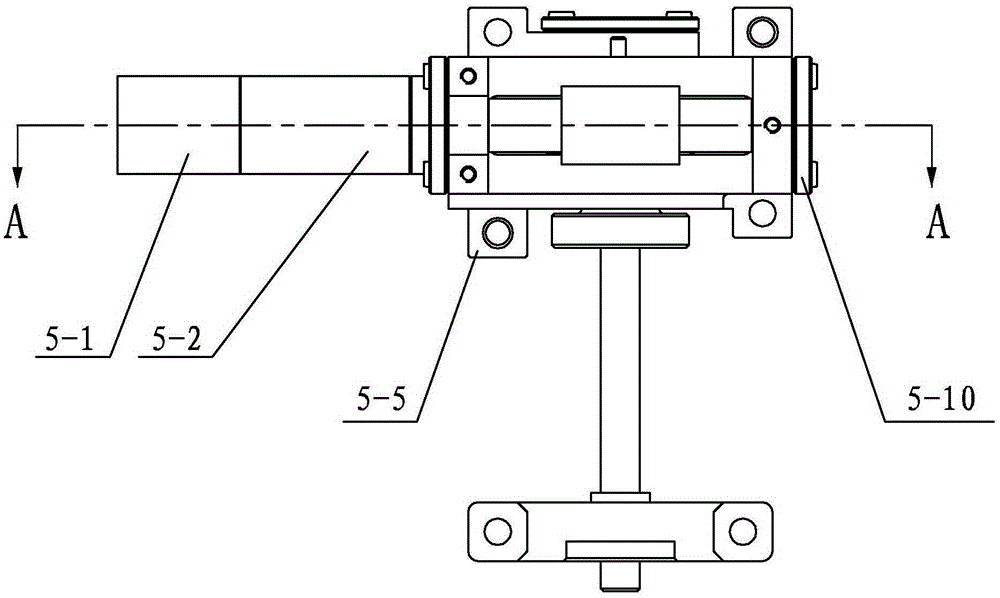
[0029] Specific implementation mode two: combination figure 1 , figure 2 , image 3 and Figure 4 Specifically explain this embodiment, the worm gear transmission mechanism 5 in this embodiment also includes a reducer end cover 5-3, a positioning sleeve 5-4, two worm shaft bearings 5-6 and a worm end cover 5-10, The reducer 5-2 is threadedly connected with the reducer end cover 5-3, the reducer end cover 5-3 is fixedly installed on the integral box body 5-5, and one end of the worm 5-9 passes through the type hole It is connected with the output shaft of the reducer 5-2, the other end of the worm 5-9 is connected with the integral box 5-5 through two worm shaft bearings 5-6, and the worm end cover 5-10 is fixedly installed On the integral casing 5-5.

[0030] In this embodiment, the end cover 5-3 of the reducer is fixed and installed on the integral box body 5-5 through four M1.6 flat head screws, and one end of the worm 5-9 passes through the hole and the output shaft of...

specific Embodiment approach 3

[0031] Specific implementation mode three: combination figure 1 , figure 2 , image 3 , Figure 4 , Figure 5 , Figure 6 , Figure 7 and Figure 8Specifically explaining this embodiment, the worm gear transmission mechanism 5 in this embodiment also includes a main bearing 5-11, a retaining ring 5-12, a connecting end cover 5-13, a positioning sleeve 5-14, and a main bearing 2 5 -16. Adjusting gasket 5-15, positioning bushing 5-18 and auxiliary bearing 5-19, the first main bearing 5-11 and the second main bearing 5-16 are all set on the worm gear shaft 5-17, and the The worm gear shaft 5-17 is connected with the integral casing 5-5 through the main bearing one 5-11 and the main bearing two 5-16 successively, and the said main bearing one 5-11 is sleeved with a retaining ring 5-12. Main bearing one 5-11 is fixedly installed on the worm gear shaft 5-17 through the retaining ring 5-12, and the end cover 5-13 is fixedly installed on the integral box body 5-5, and the worm...


PUM


Abstract

The invention relates to an abduction-adduction mechanism, in particular to the self-locking abduction-adduction mechanism for a thumb of a dexterous robot hand. In existing thumb mechanisms of the dexterous robot hand, the function of the movement of opposition of the human hand is difficult to realize. According to the mechanism, a gear-worm transmission mechanism is arranged on one side of a palm plate frame and is provided with a drive circuit board. A thumb supporting base is located on the other side of the palm plate frame. The palm plate frame is provided with an absolute position sensor. An output shaft of a motor is arranged coaxial with a worm and is connected to one end of the worm through a speed reducer. A worm gear shaft is arranged on the side, close to the palm plate frame, of the thumb supporting base, and a dexterous robot hand thumb mechanism is arranged on the side, away from the palm plate frame, of the thumb supporting base. The absolute position sensor comprises a potentiometer and a through circuit board, wherein the potentiometer is fixedly connected to the through circuit board. A control circuit is detachably connected to an auxiliary base. The self-locking abduction-adduction mechanism is used for controlling the movement of opposition of the dexterous robot hand thumb mechanism.

Description

technical field [0001] The invention specifically relates to a self-locking abduction and adduction mechanism for the thumb of a robot dexterous hand. Background technique [0002] With the advancement of society and the continuous deepening of human exploration of unknown fields, such as space environment and nuclear environment, traditional robot end effectors have been unable to meet complex environments and tasks due to their shortcomings such as single grasping method and lack of flexibility. demand. The multi-fingered robot dexterous hand has multiple degrees of freedom and multi-sensory functions, and has good grasping and manipulation performance in complex environments and tasks. Its research has attracted more and more attention, but there are not many studies on the thumb mechanism. In fact, it is thanks to the thumb that the human hand can achieve both strong grasping and precise operation. The movement of opposition between the thumb and the remaining four fin...

Claims


Application Information

Patent Timeline
IPC IPC(8): B25J15/00
CPCB25J15/0009
Inventor 樊绍巍王海荣石琳顾海巍刘宏
Owner HARBIN INST OF TECH
Why Eureka
Try Eureka