Sucker grip

A suction cup and body technology, applied in the field of suction cup grippers, can solve the problems of potential safety hazards, low work efficiency, and high labor intensity of manual handling of cartons, and achieve the effects of wide application range, high work efficiency, and convenient and reliable installation or disassembly

Inactive Publication Date: 2016-03-16
HEFEI OBOTE AUTOMATION EQUIP
View PDF4 Cites 0 Cited by
  • Summary
  • Abstract
  • Description
  • Claims
  • Application Information

AI Technical Summary

Problems solved by technology

Manually moving cartons is labor-intensive, low-efficiency, and poses potential safety hazards

Method used


Image

  • Sucker grip
  • Sucker grip

Examples


Embodiment Construction

[0017] In order to make the technical means, creative features, goals and effects achieved by the present invention easy to understand, the present invention will be further described below in conjunction with specific illustrations.

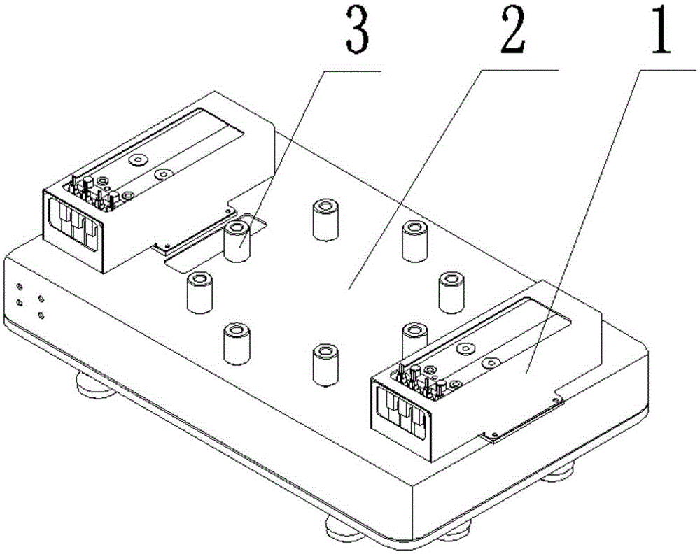
[0018] Such as figure 1 As shown, a sucker gripper includes a gripper body 2, the upper part of the gripper body 2 is provided with a vacuum generator 1, the center of the upper part of the gripper body 2 is provided with a flange connector 3, and the lower part of the gripper body 2 is provided with There are two suction cups 4 and two vacuum generators 1, which are respectively located at the two ends of the handle body 2.

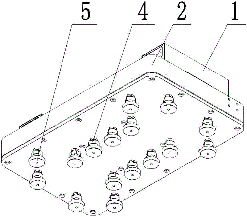
[0019] Such as figure 2 As shown, there are sixteen suction cups 4, four suction cups 4 are arranged at the left and right ends of the lower part of the gripper body 2, and eight suckers 4 are evenly arranged near the center of the gripper body 2 lower part; the suction cups 4 are provided with pad covers 5, The pad cov...


PUM


Abstract

The invention provides a sucker grip, and belongs to the technical field of carton carrying. The sucker grip comprises a grip body, wherein a vacuum generator is arranged on the upper part of the grip body; a flange connecting piece is arranged in the center of the upper part of the grip body; and a sucker is arranged on the lower part of the grip body. The problem that working efficiency of manual carton carrying is low is solved. The sucker grip can suck various types of cartons, and is wide in using range; when the sucker sucks goods, the goods cannot be damaged; the sucker is safe and reliable in operation, high in working efficiency and low in noise; and because the sucker is easy to damage, a cushion cover for protecting the sucker is arranged on the outside of the sucker, and can be directly changed if the cushion cover is damaged, the sucker is not required to be changed, and the using cost is reduced. The sucker grip is reliable and convenient to mount or dismount, and is convenient to repair.

Description

technical field [0001] The invention belongs to the technical field of carton handling, and in particular relates to a suction cup gripper. Background technique [0002] When factories move cartons, they usually move them manually. Manually moving cartons is labor-intensive, low-efficiency, and poses potential safety hazards. Contents of the invention [0003] The technical problem to be solved by the present invention is to provide a mechanical handling device with high working efficiency, that is, a sucker gripper. [0004] The technical problem to be solved by the present invention adopts the following technical solutions to realize: [0005] A suction cup gripper comprises a gripper body, a vacuum generator is arranged on the upper part of the gripper body, a flange connector is arranged at the center of the upper part of the gripper body, and a suction cup is arranged on the lower part of the gripper body. [0006] There are two vacuum generators, which are respect...

Claims


Application Information

Patent Timeline
IPC IPC(8): B65G61/00
CPCB65G61/00
Inventor 胡小强缪忠源倪亚
Owner HEFEI OBOTE AUTOMATION EQUIP
Why Eureka
Try Eureka