
High-flow safety valve

A large-flow safety valve and spool technology, which is applied in mining equipment, earthwork drilling, pillars/supports, etc., can solve the problem that the safety valve affects the normal operation of the hydraulic support and personnel safety, affects the dynamic response time of the safety valve, and the overshoot of the valve body. Liquid and seal diameter problems, etc., to prevent random disassembly structure, improve dynamic response time, improve the effect of reliability

Active Publication Date: 2016-03-16
BEIJING TIANMA INTELLIGENT CONTROL TECH CO LTD
View PDF6 Cites 6 Cited by
  • Summary
  • Abstract
  • Description
  • Claims
  • Application Information

AI Technical Summary

Problems solved by technology

The performance of the safety valve directly affects the normal operation of the hydraulic support and the safety of personnel. With the application of the large mining height and caving support, the working resistance continues to increase, and the continuous change of the working environment affects the stability of the safety valve performance. , dynamic performance and life requirements are getting higher and higher, and its development trend is high pressure and large flow safety valve, which brings challenges to safety valve design, processing and technology
[0003] With the continuous increase of the initial support force of the hydraulic support and the diameter of the column, the requirements for the nominal flow rate of the safety valve are also getting higher and higher. However, the large flow safety valves on the existing market mainly adopt mechanical spring structures. The increase of the nominal pressure leads to a larger diameter of the valve body through liquid and sealing, and the spring required for the large-flow safety valve also increases with the pre-compression force, resulting in an increasing rigidity, volume and weight, and its design and processing are also more difficult. It is becoming more and more obvious that the spring becomes a bottleneck in the integrated design of the high flow safety valve
[0004] The traditional sealing form of the safety valve for the column mainly adopts the sealing form of the valve core through the liquid hole. During the opening process of the safety valve, there is inevitably a dead zone stroke, which seriously affects the dynamic response time during the opening process of the safety valve, resulting in the pressure of the column. momentary pressure phenomenon

Method used


Image

  • High-flow safety valve

Examples


Embodiment Construction

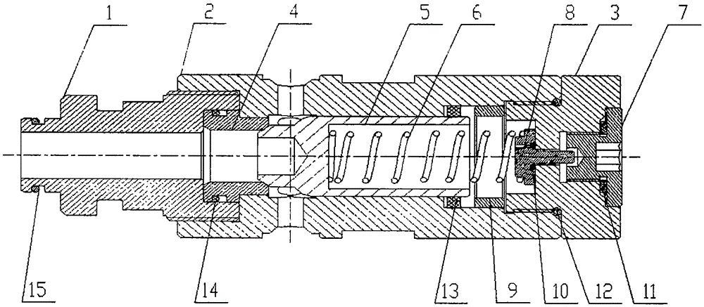
[0024] Attached below figure 1 An exemplary detailed description of the invention is given.

[0025] See attached figure 1 , which describes a preferred embodiment of the high flow safety valve according to the invention. The high-flow safety valve includes a valve body, a valve seat, a joint, a terminal, a valve core, a spring, and a floating sleeve. The joint and the terminal are respectively threaded at both ends of the valve body. The seat is set on the side close to the joint, the valve core is set on the side close to the end, and the line sealing contact between the valve seat and the valve core; the valve core is connected to the end through a spring, one end of the spring is connected to the inner surface of the inner hole of the valve core, and the other end There is a floating sleeve between the end and the valve body, which is used to prevent the back pressure from being greater than the inflation pressure and cause the third sealing ring to recoil to the inside ...


PUM


Abstract

A high-flow safety valve comprises a valve body, a valve seat, a connector, an end, an ejector rod, a valve element, a spring and a floating sleeve. The connector and the end are in threaded connection with the two ends of the valve body respectively. The valve seat and the valve element are arranged in the valve body. A sealing gasket is arranged between the end and a tail end screw. A first sealing ring is arranged between the ejector rod and the end. An inner counter bore is formed in the end face of the side, facing the connector, of the valve element. The valve seat and the valve element are in linear sealing contact. A sealing ring is arranged between the valve element and a spring cavity. The valve element is connected with the end through the spring. The floating sleeve is arranged between the end and the valve body. A metal hard sealing structural form is adopted for replacing a traditional O ring soft seal form; a sealing gas spring form is adopted for replacing a traditional mechanical spring structure; inflation pressure is lowered, and inflation sealing reliability is improved; the end is in a smooth cylinder shape, and the structural form is prevented from being freely demounted; and meanwhile it is guaranteed that in the process of forcefully loosening the end, before a thread is not screwed out of the valve body, gas is leaked, and the operation safety of personnel is guaranteed.

Description

technical field [0001] The invention relates to a large-flow safety valve, in particular to a safety protection system for fully mechanized mining face equipment such as column jacks, so as to avoid excessive pressure of the protected system. Background technique [0002] The safety valve is an automatic pressure relief device driven by medium pressure. As a protective component of the hydraulic support, it has the characteristics of high safety margin, fast response, reliable sealing form, and strong anti-pollution ability. It is mostly used in the lower cavity of the column, balance The upper and lower chambers of the jack, the piston chamber or piston rod chamber of the push jack, etc. The performance of the safety valve directly affects the normal operation of the hydraulic support and the safety of personnel. With the application of the large mining height and caving support, the working resistance continues to increase, and the continuous change of the working environm...

Claims


Application Information

Patent Timeline
Patent Type & Authority Applications(China)
IPC IPC(8): E21D15/51
CPCE21D15/51
Inventor 韦文术周如林王伟刘晓萌李然苏哲
Owner BEIJING TIANMA INTELLIGENT CONTROL TECH CO LTD
Learn More