
Micro-field emission electric thruster with blade type porous material emitter array

A porous material and electric thruster technology, which is applied in the field of satellite launch, can solve the problems of small effective launch area, small thrust, large thruster size and weight, and achieve high propellant launch density, reduced size and weight, and thrust high density effect

Active Publication Date: 2016-03-16
SHANGHAI INST OF SPACE PROPULSION
View PDF4 Cites 3 Cited by
  • Summary
  • Abstract
  • Description
  • Claims
  • Application Information

AI Technical Summary

Problems solved by technology

[0006] (1) The current needle-type field emission electric thruster uses a single or multiple emitting needles as the emitter. Due to the small effective emission area, the thrust is small (generally, the thrust generated by a single emitting needle is 20-50μN)
In addition, due to the long launch needle and the need for fine assembly, the size and weight of the thruster are relatively large. It is more difficult to use it for tiny satellites weighing less than 50kg, and it is even more difficult to perform orbit transfers and other occasions that require high thrust.
[0007] (2) Narrow-slit field emission electric thruster adopts narrow-slit emitter, and its effective emission area is larger than that of needle-type field emission electric thruster, so the thrust is large. The heavy weight leads to a large size and weight of the thruster. When used for tiny satellites with a weight of 10-50 kg, there are problems such as weight and size are too large, and it is more difficult to use for satellites below 10 kg.
[0008] In summary, the current field emission electric thruster structure is difficult to miniaturize, and it is difficult to meet the needs of micro-satellites weighing less than 50kg

Method used


Image

  • Micro-field emission electric thruster with blade type porous material emitter array
  • Micro-field emission electric thruster with blade type porous material emitter array
  • Micro-field emission electric thruster with blade type porous material emitter array

Examples


Embodiment 1

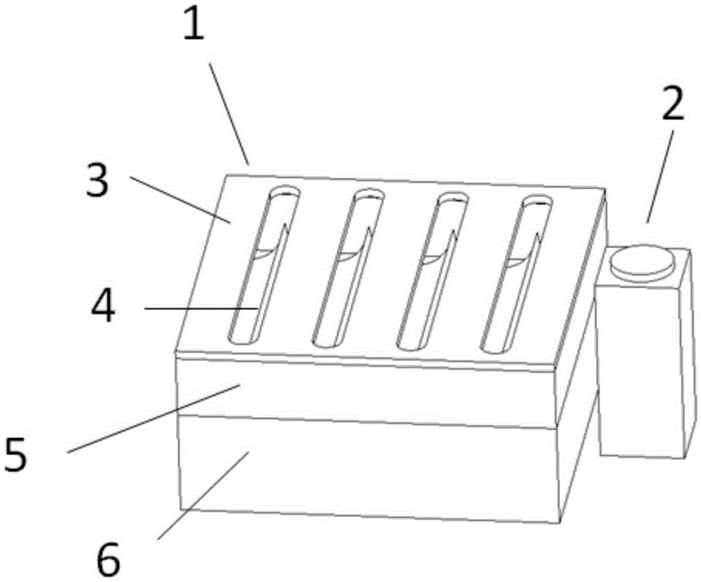
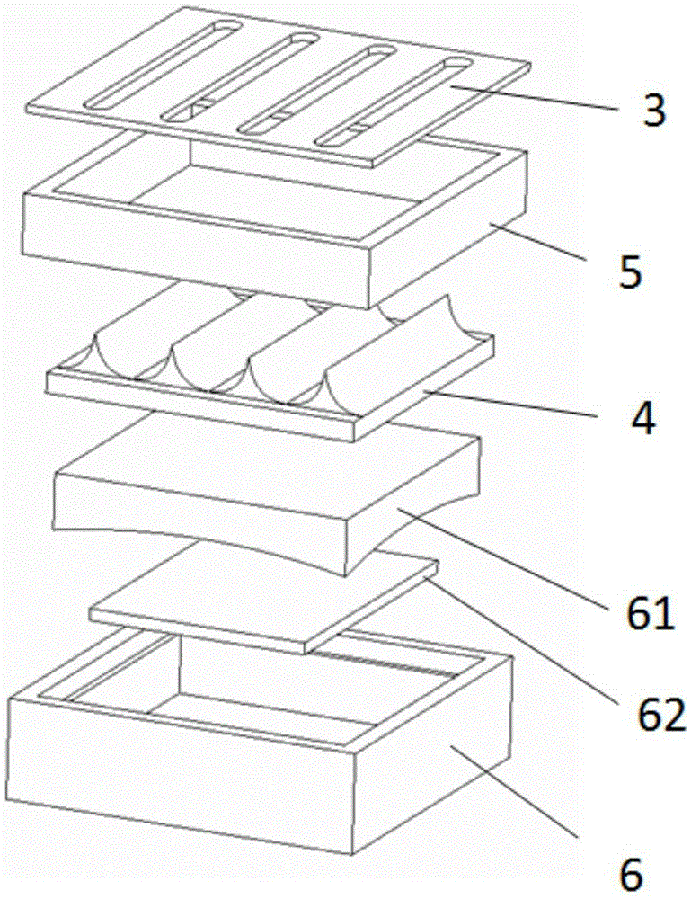
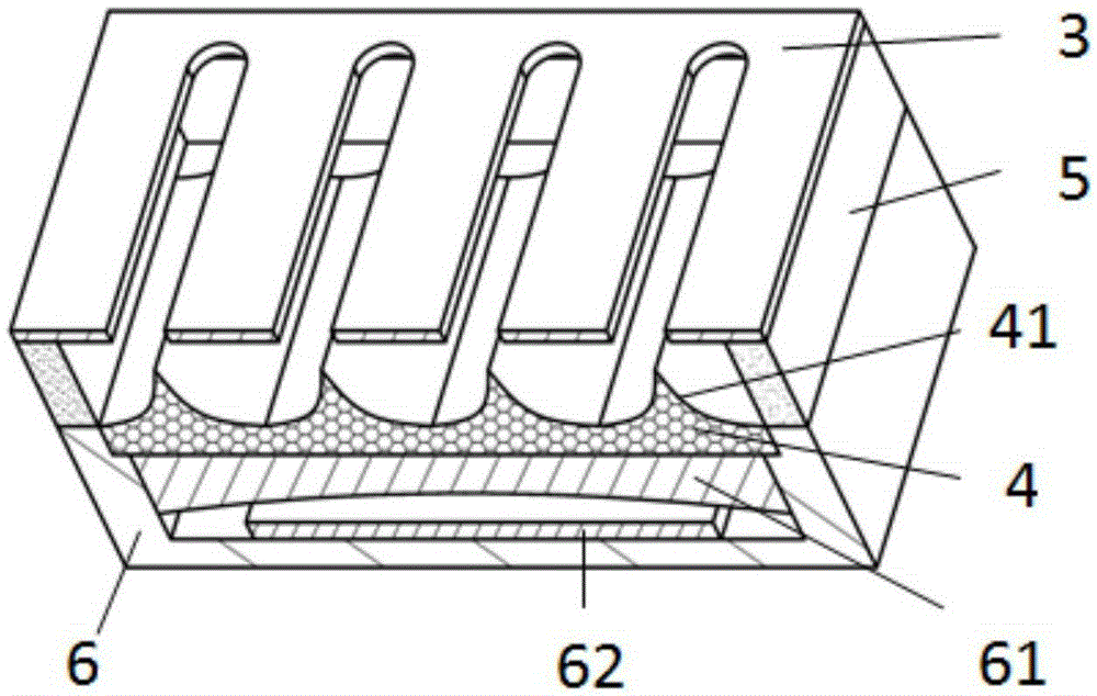
[0031] The present invention provides a kind of blade type porous material emitter array miniature field emission electric thruster aiming at the existing deficiencies, such as figure 1 , figure 2 with image 3 As shown, it includes a neutralizer 2 and a thruster main body 1 connected to each other, the neutralizer 2 emits electrons to neutralize the beam current, and the main body of the thruster 1 includes grids 3 that are mated and connected sequentially from top to bottom , an insulating support 5 and a propellant storage chamber 6, the insulating support 5 is a frame structure, the insulating support 5 is provided with an emitter array 4 matching the grid 3, and the emitter array 4 is provided below Cooperating heater 62 and propellant 61 , the propellant 61 and heater 62 are located in the propellant storage chamber 6 . Wherein, a negative voltage is applied to the gate 3 , the gate 3 has a planar structure, and four gate holes are arranged on the gate 3 .

[0032] W...

Embodiment 2

[0039] The present invention also provides a blade-type porous material emitter array miniature field emission electric thruster, such as Figure 5 As shown, the lower surface of the emitter array is an inner concave surface.

[0040] Other structures in this embodiment are the same as those in Embodiment 1, and will not be described in detail in this embodiment.

Embodiment 3

[0042] The present invention also provides a blade-type porous material emitter array miniature field emission electric thruster, such as Image 6 As shown, the heater 62 is arranged on the lower side of the propellant 61 .

[0043] Other structures in this embodiment are the same as those in Embodiment 1, and will not be described in detail in this embodiment.


PUM


Abstract

The invention discloses a micro-field emission electric thruster with a blade type porous material emitter array. The micro-field emission electric thruster comprises a neutralizer and a thruster main body, the two of which are connected with each other; the thruster main body comprises a grid electrode, an insulating support and a propellant storage chamber, all of which are matched and connected with each other in order from top to bottom; the insulating support is of a frame-shaped structure; a blade type emitter array matched with the grid electrode is arranged within the insulating support; matched heater and propellant are arranged below the emitter array; the propellant and the heater both are located within the propellant storage chamber; as a result, the minimization of the structure of the field emission electric thruster is realized to meet the requirements of micro-satellites having a weight of less than 50kg.

Description

technical field [0001] The invention relates to the technical field of satellite launch, in particular to a blade type porous material emitter array miniature field emission electric thruster. Background technique [0002] At present, micro-satellites with high functional integration have become a reality and are developing very rapidly, especially micro-satellites with a weight of 1-50kg. Due to the short development cycle, low development and launch costs, flexible launch, and difficult detection, micro-satellites can form a "virtual large satellite" in the form of a constellation and form a "virtual large satellite" in the form of a constellation, such as Large-scale remote sensing has been highly valued by countries all over the world, and the number of launches has increased rapidly in recent years. However, most of the microsatellites below 50 kg are not equipped with propulsion systems, and some are equipped with low-performance cold air propulsion systems or single-...

Claims


Application Information

Patent Timeline
IPC IPC(8): F03H1/00
Inventor 杭观荣张岩梁伟乔彩霞薛伟华戴佳康小录康小明郭登帅
Owner SHANGHAI INST OF SPACE PROPULSION
Learn More