A low-angle light source with adjustable height and adjustable guide rod

A technology for adjusting angles and low angles, applied in the field of light sources for optical instruments, can solve problems such as low adjustment efficiency and low adjustment control accuracy, and achieve the effect of improving measurement accuracy

Active Publication Date: 2017-08-25
江西金酷智能制造有限公司
View PDF2 Cites 0 Cited by
  • Summary
  • Abstract
  • Description
  • Claims
  • Application Information

AI Technical Summary

Problems solved by technology

[0006] In order to solve the problems in the prior art that the incident angle of the light source, the height of the light source and the irradiation range of the image measuring instrument are fixed, or the incident angle is adjusted manually, the adjustment efficiency is low and the adjustment control accuracy is low, the present invention provides a A guide rod-type low-angle light source with adjustable height and adjustable angle, which has a high degree of mechanization and controllable precision

Method used


Image

  • A low-angle light source with adjustable height and adjustable guide rod
  • A low-angle light source with adjustable height and adjustable guide rod
  • A low-angle light source with adjustable height and adjustable guide rod

Examples


Embodiment 1

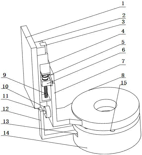
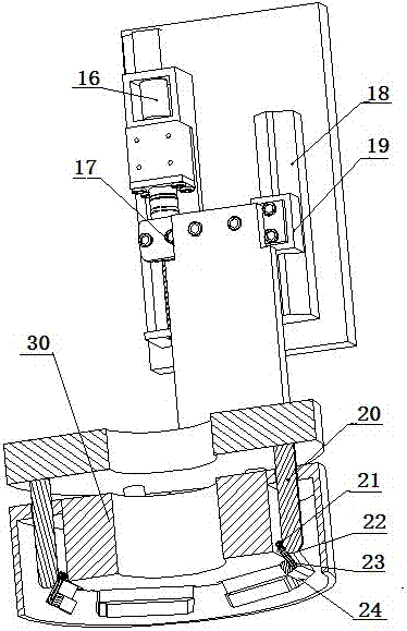
[0019] Such as figure 1 and figure 2 As shown, the low-angle light source includes a stand 30, a guide rod 20, a lampshade 14, a lamp holder 23, a lamp strip 24, a pressure plate 8, an electromagnetic module 10, a driving mechanism, a magnet device, a connecting plate I7 ​​and a connecting plate II12, and a guide rod 20 is fixedly connected with the pressure plate 8, the connection plate I7 ​​is fixedly connected with the pressure plate 8, the upper end of the connection plate I7 ​​is connected with the driving mechanism, the driving mechanism makes the connection plate I7 ​​move up and down, the upper end of the lampshade 14 has a guide hole 15 for the guide rod 20 to move up and down, the lampshade 14 is fixed on the stand 30, there is a hole 13 on the side of the lampshade 14, the connecting plate II12 passes through this hole and is fixed on the stand 30, the light strip 24 is fixedly connected to the lamp holder 23, and the lamp holder 23 is rotatably fixed on the stand ...

Embodiment 2

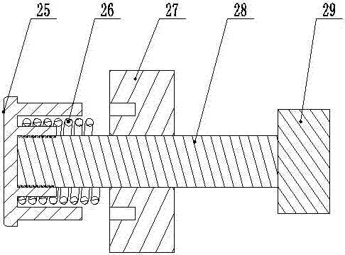
[0026] Such as Figure 4 As shown, different from Example 1, the connecting plate I7 ​​and the connecting plate II12 are respectively connected to the driving mechanism and driven separately. When the height is adjusted, the two move up and down together at the same speed. Driven up and down, same as above. The movement coordination between the connecting plate I7 ​​and the connecting plate II12 can be realized through electric control.


PUM


Abstract

The invention belongs to the technical field of light sources of a measurement instrument, and relates to a guide rod type height and angle adjustable low-angle light source. A guide rod is fixedly connected with a pressing plate, a first connecting plate is fixedly connected with the pressing plate, and the upper end of the first connecting plate is connected with a driving mechanism; a guide hole allowing the guide rod to vertically move is formed in the upper end of a lampshade which is fixed to a vertical seat, a hole is formed in the side edge of the lampshade, and a second connecting plate penetrates the hole to be fixed to the vertical seat; a lamp strip is fixedly connected to a lamp holder which is rotatably fixed to the vertical seat, a sliding groove is formed in the upper end of the lamp holder, and the lower end of the guide rod is located in the sliding groove; and the second connecting plate and the first connecting plate are connected through an electromagnetic module, and a magnet device is arranged below the vertical seat. The guide rod and the vertical seat synchronously move to adjust the height, the guide rod independently moves to adjust the angle, and the aim that the guide rod and the vertical seat share one driving mechanism is achieved through the electromagnetic module.

Description

technical field [0001] The invention relates to a light source for optical instruments, belonging to the technical field of measuring light sources. Background technique [0002] The image measuring instrument is a qualitative leap on the basis of the digital display projector, and it is an upgraded version of the projector. It overcomes the shortcomings of traditional projectors and is a new type of high-precision, high-tech measuring instrument integrating optical, mechanical, electrical, and computer image technologies. It uses an optical lens to perform high-magnification magnification imaging on the object to be measured. After the enlarged object image is sent to the computer through the CCD camera system, it can efficiently detect the contours and surface shapes, dimensions, angles and positions of various complex workpieces. Microscopic inspection and quality control of parts. It is widely used in the measurement of mobile phone accessories, home appliances, connec...

Claims


Application Information

Patent Timeline
Patent Type & Authority Patents(China)
IPC IPC(8): F21S8/00F21V14/02
CPCF21S8/00F21V14/02
Inventor 马辉何建涛叶向阳宋杰董春龙周自吉
Owner 江西金酷智能制造有限公司
Why Eureka
Try Eureka