Walking track base backscattering imager

A backscattering and walking technology, which is applied in the fields of instruments, scientific instruments, nuclear radiation exploration, etc., can solve the problems of large size, inconvenient transportation, X-ray leakage, etc., and achieve remote control operation, easy transportation and high stability Effect

Active Publication Date: 2016-03-16
PURPLE SQUARE TECH
View PDF6 Cites 16 Cited by
  • Summary
  • Abstract
  • Description
  • Claims
  • Application Information

AI Technical Summary

Problems solved by technology

The subway security inspection system uses the conveyor belt to send the detected object into the crawler channel for detection. Its advantage is that it has high detection efficiency and can perform flow-through detection on the luggage of floating personnel. It can only detect objects that can be placed in the channel, and there is a limit to the volume of the detected object. The equipment itself has weak protection against X-rays, and X-rays are easy to leak from the entrance and exit of the conveyor belt.
The advantage of portable X-ray detector is that it is easy to carry. Each instrument is equipped with a detection box, an X-ray machine and several power accessories. It only needs one or two people to carry it to the place of use. The disadvantage is that the detection area depends on The size of the detection box cannot detect larger objects, and because the detection object needs to be placed between the X-ray machine and the detection box during detection, it cannot detect objects such as walls, and the equipment itself has basically no protection against X-rays. The operator needs to stay away from the equipment to avoid being affected by X-rays

Method used


Image

  • Walking track base backscattering imager
  • Walking track base backscattering imager
  • Walking track base backscattering imager

Examples


Embodiment Construction

[0021] The following clearly and completely describes the technical solutions in the embodiments of the present invention. Obviously, the described embodiments are only some of the embodiments of the present invention, but not all of them. Based on the embodiments of the present invention, all other embodiments obtained by persons of ordinary skill in the art without making creative efforts belong to the protection scope of the present invention.

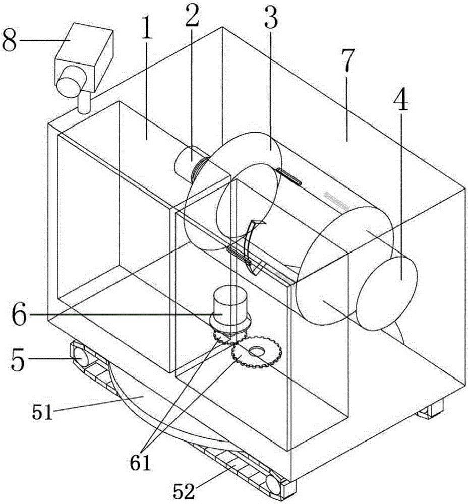
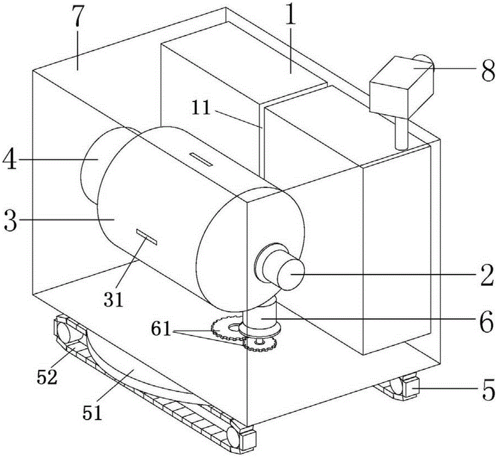
[0022] Such as figure 1 , 2 As shown, the embodiment of the present invention provides a walking crawler base backscatter imager, including:

[0023] Shielding shell, the bottom of which is provided with a turntable crawler base, the shielding shell is provided with a base driving device and a transmission part that drives the rotating disc type crawler base to drive the shielding shell to rotate and move; preferably, the base driving device 6 adopts a motor, and the transmission part 61 adopts transmission gear;

[0024] The det...


PUM


Abstract

The invention discloses a walking track base backscattering imager, which comprises a shielding shell, a detector, an X ray machine, a drum, a drum driving device, and a driving control device, wherein the bottom part of the shielding shell is provided with a turntable track base, and the turntable track base is internally provided with a base driving device driving the turntable track base to drive the shielding shell to rotate and move and a driving part; the detector is arranged at one side inside the shielding shell for acquiring an image and processing the image into a complete image; the X ray machine is arranged inside the shielding shell and located beside the detector, and the light-emitting face of the X ray machine faces the detector; the drum covers the light-emitting face of the X ray machine and rotates around the light-emitting face of the X ray machine, a light outgoing port is arranged on the drum, and the light outgoing port is corresponding to the detector; the drum driving device is connected with the drum for driving the drum to rotate at a constant speed; and the driving control device respectively controls the base driving device and the drum driving device. The imager has the advantages that the detection area is large; a wall can be detected; operation on a wild rugged road surface can be realized; the detector can be rotated to image a fan-shaped area; and X rays can be well protected.

Description

technical field [0001] The invention belongs to the field of safety monitoring equipment, and relates to a walking type backscatter imaging equipment using X-ray backscatter imaging. Background technique [0002] Implementing non-contact security checks on personnel, luggage and containers entering important places has become the most widely used security check measure at present. All kinds of metal or non-metal weapons, poisons and explosives are the focus of detection. At present, X-ray transmission imaging technology is most used. The principle is that X-rays have a strong penetrating ability. When passing through materials with different densities, the intensity of transmitted light is different, and the intensity of light received by the receiver is different. When the signal becomes large, it can be imaged. X-ray imaging equipment is widely used in subway security inspection systems and portable X-ray detectors. The subway security inspection system uses the conveyo...

Claims


Application Information

Patent Timeline
Patent Type & Authority Applications(China)
IPC IPC(8): G01V5/00
CPCG01V5/0025
Inventor 林勇王建国
Owner PURPLE SQUARE TECH
Why Eureka
Try Eureka