Assistant-returning magnetic approximate switch

A technology of magnetic proximity switch and booster lever, which is applied in the direction of magnetic switch, permanent magnet reed switch, magnetic/electric field switch, etc., can solve the problem of electroplating layer falling, booster lever torque conversion and stroke boosting effect is not obvious, affecting the product Work stability and service life and other issues, to achieve the effect of reasonable structure, improve work stability and service life

Active Publication Date: 2016-03-16
FOSHAN YIFU TECH CO LTD +1
View PDF4 Cites 9 Cited by
  • Summary
  • Abstract
  • Description
  • Claims
  • Application Information

AI Technical Summary

Problems solved by technology

However, the swing fulcrum of the booster lever, the torque fulcrum of the booster part and the elastic tongue are on the same horizontal line, and the moment arm between the moment fulcrum and the swing fulcrum is longer, and the control stroke of one end of the booster rod in the limit mechanism is the same as the swing of the booster part. The ratio between the strokes is relatively large, resulting in insignificant torque conversion and stroke boosting effects of the booster lever; the magnet moves up and down against the booster lever to make it swing and trigger the shrapnel action, and there is a certain relative friction between the magnet, the housing, and the booster lever , it is easy to produce magnetic powder or the drop of the electroplating layer on the component, which affects the reliability of the electrical connection between the shrapnel and the contact on the terminal piece; although the torque conversion of the booster lever ensures the trigger stability of the large current on-off control, the contact The arcing phenomenon generated when the current load changes has not been well resolved, and the surface oxidation problem of contacts and metal parts always exists, which affects the working stability and service life of the product

Method used


Image

  • Assistant-returning magnetic approximate switch
  • Assistant-returning magnetic approximate switch
  • Assistant-returning magnetic approximate switch

Examples


Embodiment Construction

[0023] The technical solutions of the present invention will be described below in conjunction with the accompanying drawings and embodiments.

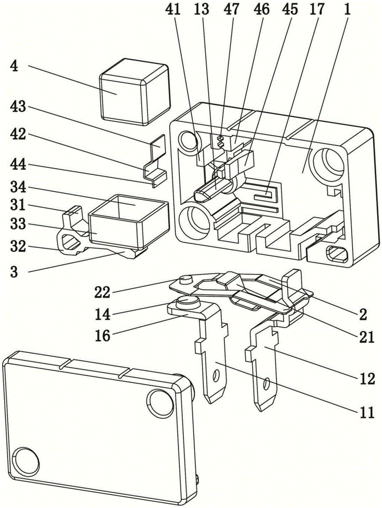
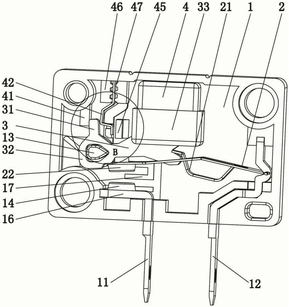
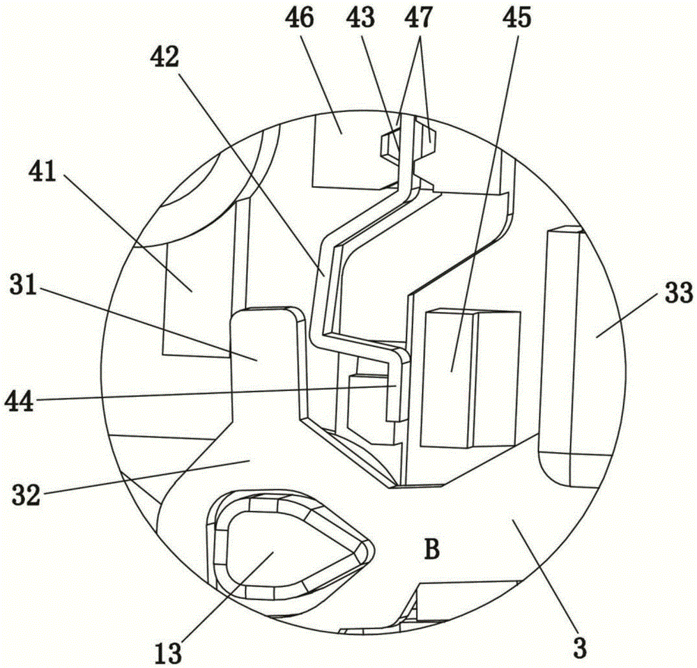
[0024] Such as Figure 1-3 As shown, a power-assisted return magnetic proximity switch according to the present invention includes a housing 1, a magnet 4, a first terminal 11 and a second terminal 12 are arranged in the inner cavity of the housing 1, and the first terminal 11 and the second terminal 12 The second terminals 12 are arranged side by side at intervals and respectively vertically penetrated on the lower end plate of the housing 1; the upper end of the second terminal 12 is provided with an elastic contact piece 2 transversely, and the movable end of the elastic contact piece 2 is arranged on the first terminal 11 above; the housing 1 is provided with a booster rod 3, and the outer end of the booster rod 3 is hinged with the housing 1; the elastic contact piece 2 is provided with an elastic tongue 21, and the free end of t...


PUM


Abstract

The invention relates to the technical field of a magnetic switch, in particular to an assistant-returning magnetic approximate switch. The magnetic approximate switch comprises a shell, wherein a magnet, a first terminal and a second terminal are arranged in an inner cavity of the shell, an elastic contact piece is transversely arranged at the upper end of the second terminal, an assistant rod is arranged in the shell, an elastic tongue piece is arranged on the elastic contact piece, a limiting insertion plate is arranged at the outer end of the assistant rod and forms an L-shaped integral structure with the assistant rod, an assistant returning mechanism is arranged in the shell above the outer end of the assistant rod and matched with the limiting insertion plate, and the magnet is arranged between the assistant rod and an upper end plate of the shell and is in integral linkage with the assistant rod. The magnetic approximate switch is reasonable in structure; with the matching of the limiting insertion piece and the assistant returning mechanism, the control on a travelling include angle between the assistant rod and the magnet is achieved, and the reset action of the elastic tongue piece is matched during disconnection; the magnet is integrally and freely rotated with the assistant rod by a tray, and thus, the electrical connection reliability of a contact point is improved; and a guide arc groove protection structure is arranged during the disconnection travelling of the contact point, thus, the working stability of the approximate switch is improved, and the service lifetime of the approximate switch is prolonged.

Description

technical field [0001] The invention relates to the technical field of magnetic switches, in particular to a power-assisted return magnetic proximity switch. Background technique [0002] The magnetic proximity switch is a kind of proximity switch. The proximity switch is one of many types in the sensor family. It can sense the change of the positional relationship through the magnetic element, and convert the non-electric or electromagnetic quantity into the required electrical signal, so as to achieve control. or measurement purposes. For robot application technology, automatic navigation and position detection are the core technologies to realize intelligent control, and the position detection and execution control scheme provided by the proximity switch has advantages that other controllers do not have. Moreover, magnetic proximity switches are widely used in military fields such as magnetic fuze warheads, magnetic detection mines, and spacecraft fluxgates, high-end equ...

Claims


Application Information

Patent Timeline
Patent Type & Authority Applications(China)
IPC IPC(8): H01H36/00H01H5/18
CPCH01H5/18H01H36/00H01H5/24H01H9/46H01H36/0073H01H36/0006
Inventor 刘利
Owner FOSHAN YIFU TECH CO LTD
Why Eureka
Try Eureka