
Anti-PID device, anti-PID photovoltaic grid-connected power generation system and anti-PID method

A technology of grid-connected power generation and photovoltaic panels, applied in the field of anti-PID device and anti-PID, can solve the problem of high cost and achieve the effect of preventing PID effect

Active Publication Date: 2016-03-16
SUNGROW POWER SUPPLY CO LTD
View PDF4 Cites 4 Cited by
  • Summary
  • Abstract
  • Description
  • Claims
  • Application Information

AI Technical Summary

Problems solved by technology

However, there are often many photovoltaic panels in a photovoltaic grid-connected power generation system. If the materials and processes of each photovoltaic panel are improved, the cost will be too high;
[0004] 2. By configuring an anti-PID device for each photovoltaic inverter in a photovoltaic grid-connected power generation system, it is possible to avoid the PID effect of each photovoltaic panel connected to the DC side of each photovoltaic inverter. However, a photovoltaic grid-connected There are often multiple photovoltaic inverters in the power generation system. If each photovoltaic inverter is equipped with an anti-PID device, there is also the problem of high cost

Method used


Image

  • Anti-PID device, anti-PID photovoltaic grid-connected power generation system and anti-PID method
  • Anti-PID device, anti-PID photovoltaic grid-connected power generation system and anti-PID method
  • Anti-PID device, anti-PID photovoltaic grid-connected power generation system and anti-PID method

Examples


Embodiment Construction

[0030] The following will clearly and completely describe the technical solutions in the embodiments of the present invention with reference to the accompanying drawings in the embodiments of the present invention. Obviously, the described embodiments are only some, not all, embodiments of the present invention. Based on the embodiments of the present invention, all other embodiments obtained by persons of ordinary skill in the art without making creative efforts belong to the protection scope of the present invention.

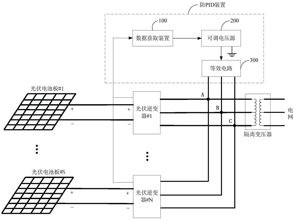
[0031] The embodiment of the present invention discloses an anti-PID device applied to a photovoltaic grid-connected power generation system that is not grounded on the DC side to prevent the PID effect of the photovoltaic panel. The structure diagram of grid-connected power generation system is as follows: figure 1 as shown ( figure 1 The direction of the arrow marked in represents the direction of signal transmission), where:

[0032] The photovoltaic grid...


PUM


Abstract

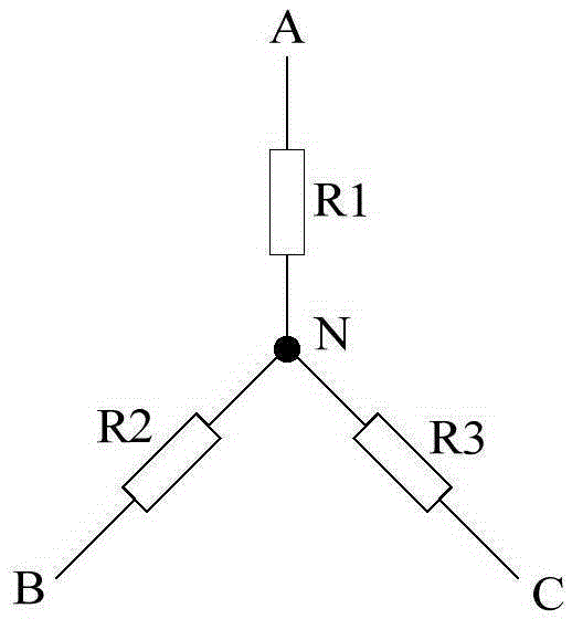
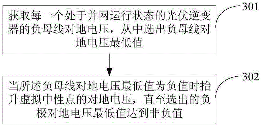
The invention discloses an anti-PID device, an anti-PID photovoltaic grid-connected power generation system and an anti-PID method. The anti-PID device is applied to a direct current-side ungrounded photovoltaic grid-connected power generation system. The anti-PID device includes a data acquisition device, an adjustable voltage source and an equivalent circuit, wherein the data acquisition device is used for acquiring negative busbar voltage to earth of each photovoltaic inverter in a grid-connected operation state, the equivalent circuit is used for constructing an equivalent neutral point of the photovoltaic grid-connected power generation system, the adjustable voltage source is used for selecting out the minimum value of the negative busbar voltage to earth which is transmitted by the data acquisition device in real time; the electric energy output end of the adjustable voltage source is connected with the equivalent neutral point constructed by the equivalent circuit; when the minimum value of the negative busbar voltage to earth is a negative value, the adjustable voltage source boosts the output voltage to earth of the adjustable voltage source itself until the minimum value of the negative busbar voltage to earth becomes a non-negative value. With the anti-PID device, the anti-PID photovoltaic grid-connected power generation system and the anti-PID method adopted, a photovoltaic panel will not generate a PID effect.

Description

technical field [0001] The invention relates to the technical field of photovoltaic power generation, and more specifically, to an anti-PID device, an anti-PID photovoltaic grid-connected power generation system and an anti-PID method. Background technique [0002] PID (potentialInducedDegradation, potential-induced decay) effect refers to the phenomenon that the performance of photovoltaic panels is reduced due to the high voltage applied to the ground. Traditional anti-PID solutions mainly include the following two types: [0003] 1. The anti-PID effect can be achieved by improving the material and process of photovoltaic panels. However, there are often many photovoltaic panels in a photovoltaic grid-connected power generation system. If the materials and processes of each photovoltaic panel are improved, the cost will be too high; [0004] 2. By configuring an anti-PID device for each photovoltaic inverter in a photovoltaic grid-connected power generation system, it is...

Claims


Application Information

Patent Timeline
IPC IPC(8): H02J3/38H02J3/12
CPCH02J3/001H02J3/12H02J3/383Y02E10/56
Inventor 李必杰王文广徐清清孙维李浩源
Owner SUNGROW POWER SUPPLY CO LTD
Learn More