
Control method for suppressing modularized multi-level current transformer output current harmonic wave

A modular multi-level, output current technology, applied in the direction of irreversible DC power input conversion to AC power output, output power conversion device, electrical components, etc., can solve the problem that the harmonic suppression effect is not obvious, the circulation suppression Increased complexity of device design, limitation of carrier frequency, etc.

Active Publication Date: 2016-03-16
HUNAN UNIV
View PDF8 Cites 14 Cited by
  • Summary
  • Abstract
  • Description
  • Claims
  • Application Information

AI Technical Summary

Problems solved by technology

When the number of output levels of the modular multilevel converter is small, large harmonics will be generated when the nearest level approximation modulation method is used. The traditional method is to change the nearest level approximation modulation method to the carrier phase shift modulation method , but the carrier phase-shift modulation strategy is limited by the carrier frequency
Another traditional method is to find out the relationship between the circulating current of the modular multilevel converter and the output voltage fluctuation, and reduce the output harmonics of the modular multilevel converter by designing a circulating current suppressor. However, in the circulating current There are many harmonic components, the analysis is more complicated, and the amount of calculation between the circulating current and the output voltage fluctuation is large, which increases the design complexity of the circulating current suppressor, which is not conducive to the design of the controller, and the harmonic suppression effect is not very obvious

Method used


Image

  • Control method for suppressing modularized multi-level current transformer output current harmonic wave
  • Control method for suppressing modularized multi-level current transformer output current harmonic wave
  • Control method for suppressing modularized multi-level current transformer output current harmonic wave

Examples


Embodiment Construction

[0040] In order to make the technical problems, technical solutions and beneficial effects solved by the present invention clearer, the present invention will be further described in detail below in conjunction with the accompanying drawings. It should be understood that the specific embodiments described here are only used to explain the present invention, not to limit the present invention.

[0041] In this embodiment, the control method of phase A is taken as an example for illustration.

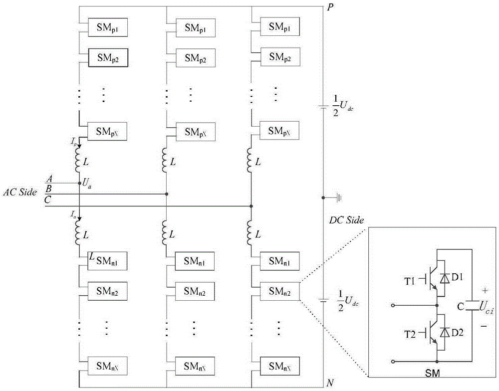
[0042] figure 1 It is a topology diagram of a modular multilevel converter, which consists of three-phase six bridge arms, and the midpoint of the DC side power supply is grounded; each bridge arm is composed of n SM sub-modules connected in series with an inductor L, and each SM sub-module is a half-bridge converter. In this implementation example, each bridge arm is composed of 9 SM sub-modules and a filter inductor L; the capacitor voltage rating of each sub-module is 50V, and the DC...


PUM


Abstract

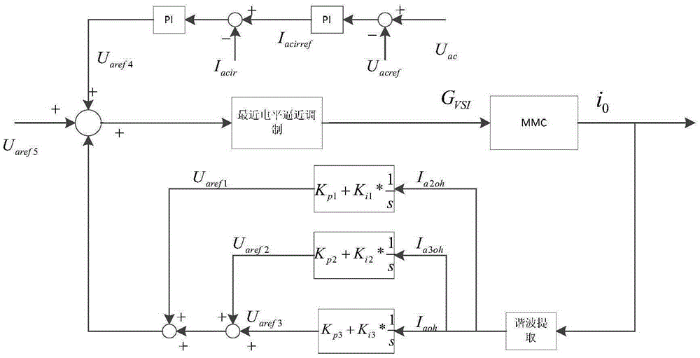
The invention discloses a control method for suppressing modularized multi-level current transformer output current harmonic wave. At first, the modularized multi-level output current is detected, a second harmonic component, a third harmonic component, and a fourth harmonic component or above are obtained by a Fourier analysis method and then are compared with 0, and the modulated voltage components of suppressed harmonic wave via a generalized frequency division PI regulator and are added to the modulated component under voltage stabilization control and the modulated component of the output voltage to obtain a total modulated voltage. After the total modulated voltage is obtained, the modulation is carried out by means of a closest level approximation method to obtain modularized multi-level current transformer triggering pulse. By means of the harmonic compensation scheme, the harmonic components, after being detected, of the output current are superposed to a control system through negative feedback, so that the output harmonic wave of the modularized multi-level current transformer can be directly and effectively suppressed.

Description

technical field [0001] The patent of the invention belongs to the field of power electronic conversion, and in particular relates to a control method for suppressing output current harmonics of a modular multilevel converter. Background technique [0002] With the increasingly serious problems of energy shortage and environmental pollution, it has become a global energy development strategy to vigorously develop and utilize renewable clean energy and advocate sustainable development of energy. However, wind power, solar power and other renewable energy power generation due to its inherent characteristics of dispersion, small size, and far away from the load center make it uneconomical to use AC transmission technology or traditional DC transmission technology for networking. However, due to the continuous expansion of the utilization scale , the grid connection of these energy sources has become an inevitable demand. Therefore, it is an urgent requirement to adopt more flex...

Claims


Application Information

Patent Timeline
IPC IPC(8): H02M7/49H02M1/12
CPCH02M1/12H02M7/49
Inventor 罗德荣荣飞李旺黄守道田新华龚喜长
Owner HUNAN UNIV
Learn More