Blast furnace overhaul method

A technology for blast furnaces and new furnaces, which is applied to blast furnaces, blast furnace details, blast furnace parts, etc., can solve the problems of not being directly applicable to blast furnaces, economic losses, shortening construction periods, etc., and achieve the effects of shortening the overhaul period, high-precision handling, and shortening the construction period

Active Publication Date: 2017-08-15
NIPPON STEEL & SUMIKIN ENG CO LTD
View PDF4 Cites 0 Cited by
  • Summary
  • Abstract
  • Description
  • Claims
  • Application Information

AI Technical Summary

Problems solved by technology

[0004] When updating the furnace body, the old furnace body is disassembled on the basis of the blast furnace setting site, and then a new furnace body is constructed. This will cause the following problems: the blowout time of the blast furnace is longer, Huge economic losses will be incurred every day of furnace shutdown
However, in Patent Document 3, the tower of the furnace body is not renewed, and it cannot be applied to the renewal of the blast furnace accompanying the expansion of the furnace body volume.
[0025] In addition, in the above-mentioned Patent Document 4, the device envisaged is a small building that can be transported by ships and vehicles. Therefore, the technology of Patent Document 4 cannot be directly applied to the renewal of blast furnaces, and needs to be expanded and contracted by the framework. As well as the disassembly and assembly of the lower device, etc., this will not bring about the effect of shortening the overhaul period
[0026] In this way, in the large-scale modular construction method shown in the above-mentioned patent document 1 or patent document 2, it is difficult to further shorten the construction period, and even if referring to patent document 3 and patent document 4 which describe the prior art, it is difficult to establish During the overhaul of the blast furnace, the old furnace body and the tower of the old furnace body are removed in a short period of time, and the new furnace body and the tower of the new furnace body are constructed

Method used


Image

  • Blast furnace overhaul method
  • Blast furnace overhaul method
  • Blast furnace overhaul method

Examples


no. 1 Embodiment approach

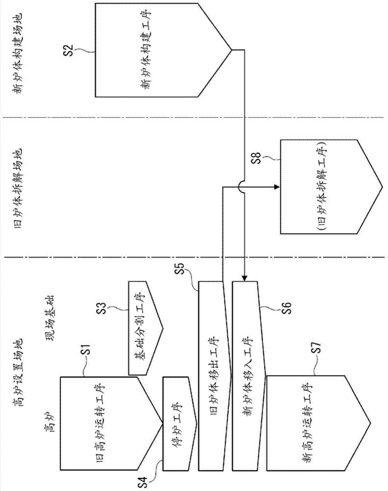
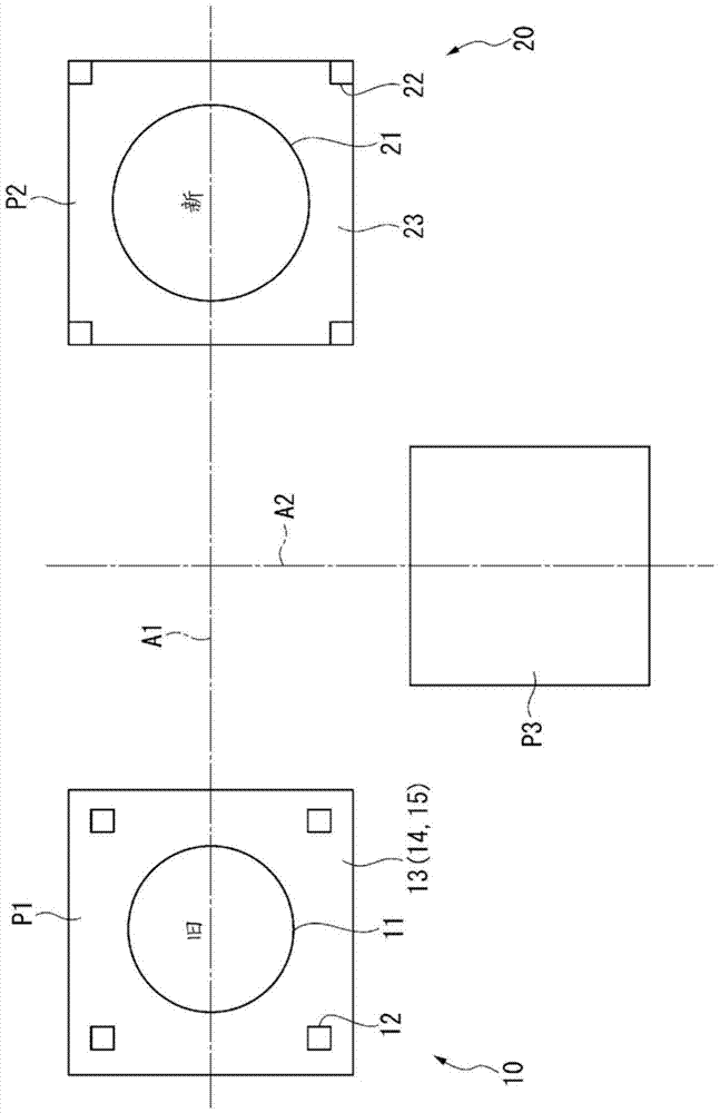
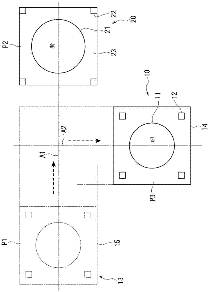
[0110] Figure 1 ~ Figure 4 Each of the figures in the figure shows the outline of the blast furnace overhaul process implemented in this embodiment ( figure 1 ), the plane configuration of the operating site used for overhaul ( figure 2 ), the removal process of the old furnace body ( image 3 ) and the new furnace body into the process ( Figure 4 ).

[0111] exist figure 2 Among them, the blast furnace (old blast furnace 10) to be overhauled in this embodiment is installed on the blast furnace installation site P1. In the blast furnace installation site P1, the old furnace body 11 and the old furnace body tower 12 are built on the site foundation 13 . The plane of the site foundation 13 is rectangular, and a new furnace body construction site P2 is set on the axis A1 perpendicular to the midpoint of one side of the plane shape of the site foundation 13 .

[0112] On the new body of furnace construction site P2, carry out the new body of furnace construction process ...

no. 2 Embodiment approach

[0253] Figure 25 and Figure 26 The second embodiment of the present invention is shown.

[0254] Similar to the above-mentioned first embodiment, this embodiment also follows Figure 1 ~ Figure 4 The general procedure shown is for a blast furnace overhaul. However, what differs from the above-mentioned first embodiment is the structure of the conveyance device 30A for removal used in the old furnace body removal process S5. Therefore, in the following description, repeated descriptions of the same matters will be omitted, and only different parts will be described.

[0255] In the above-mentioned first embodiment, the transport device 30 for removal (refer to Figure 8 ) in order to carry out the third transport operation (transport along the axis A2 direction towards the old furnace body dismantling site P3), and use the recess 33 arranged on the ground, the sliding structure part 43 arranged on the bottom surface of the recess 33 and the The fork moving stage 32 that ...

no. 3 Embodiment approach

[0265] Figure 27 ~ Figure 30 Each figure of FIG. 3 shows the 3rd embodiment of this invention.

[0266] Similar to the above-mentioned first embodiment, this embodiment also follows Figure 1 ~ Figure 4 The general procedure shown is for a blast furnace overhaul. However, the difference from the above-mentioned first embodiment is the configuration of the transfer device 30B used in the old furnace body removal step S5 and the configuration of the transfer device 39B used in the new furnace body transfer step S6. Therefore, in the following description, repeated descriptions of the same matters will be omitted, and only different parts will be described.

[0267] First, the conveyance apparatus 30B for removal used in the old furnace body removal process S5 is demonstrated.

[0268] In the above-mentioned first embodiment, the transport device 30 for removal (refer to Figure 8 ) for the first to third conveying operations has: a sliding structure part 41 (height L1) arra...


PUM


Abstract

A method for revamping a blast furnace that has a furnace body and a furnace body tower installed on a site foundation includes: while an old blast furnace is in operation (S1), a new furnace construction step (S2) of constructing a new furnace tower structure and a new furnace proper on the new foundation at a site different from the site foundation; and a foundation segmentation step (S3) of vertically cutting the site foundation to segment the site foundation into a foundation top on which the old furnace proper and the old furnace tower structure are mounted and a foundation bottom; blowing out the blast furnace (S4); an old furnace pull-out step (S5) of carrying out the foundation top integrally with the old furnace proper and the old furnace tower structure; and a new furnace pull-in step (S6) of introducing the new foundation on the foundation bottom integrally with the new furnace tower structure and the new furnace proper.

Description

technical field [0001] The invention relates to a method for overhauling a blast furnace, in particular to a method for overhauling a blast furnace capable of removing an old furnace body and a tower frame of an old furnace body in a short time and constructing a new furnace body and a tower frame of a new furnace body. Background technique [0002] For blast furnaces used for ironmaking, major repairs, that is, renewal of the furnace body, are required every ten years. [0003] Renewal of the furnace body is carried out by removing the old furnace body built on the foundation of the blast furnace installation site and constructing a new furnace body on the same foundation. [0004] When updating the furnace body, the old furnace body is disassembled on the basis of the blast furnace setting site, and then a new furnace body is constructed. This will cause the following problems: the blowout time of the blast furnace is longer, Huge economic losses will be generated every d...

Claims


Application Information

Patent Timeline
Patent Type & Authority Patents(China)
IPC IPC(8): C21B7/00
CPCC21B7/00
Inventor 高崎洋须藤雄二田后宏记
Owner NIPPON STEEL & SUMIKIN ENG CO LTD
Why Eureka
Try Eureka