Eureka AIR delivers breakthrough ideas for toughest innovation challenges, trusted by R&D personnel around the world.

Sectional adjustable artificial hip joint prosthesis

A hip joint prosthesis and adjustable technology, applied in the direction of hip joints, prostheses, joint implants, etc., can solve problems such as inability to perfectly adapt to individual differences, lumbar muscle swelling, and loose prostheses, and achieve functional rehabilitation and improvement Promote the long-term prognosis of patients, improve the effect of secondary fractures, and firm internal fixation

Inactive Publication Date: 2016-03-23
陈卫 +1
View PDF7 Cites 7 Cited by
  • Summary
  • Abstract
  • Description
  • Claims
  • Application Information

AI Technical Summary

Problems solved by technology

[0003] Although several major improvements have been made, due to the special shape of the femoral neck, the two special angles, the neck-shaft angle (about 110°-140°) and the anteversion angle (normally 12°-15°), are mostly due to Individual differences vary, and the existing artificial hip joint prosthesis cannot perfectly adapt to the above-mentioned individual differences due to the one-piece fixed structure
Moreover, in the current clinical hip replacement surgery, the placement angle of the artificial hip joint prosthesis mainly depends on the operator's experience and feeling, and a slight difference may cause some unique defects of hip joint replacement surgery, such as prosthesis loosening As well as secondary fractures, osteonecrosis, etc., there are even some rare but objective problems, such as the fracture of the central stabilizing bracket placed in the prosthesis, lumbar muscle swelling, etc.

Method used


Image

  • Sectional adjustable artificial hip joint prosthesis
  • Sectional adjustable artificial hip joint prosthesis
  • Sectional adjustable artificial hip joint prosthesis

Examples


Embodiment 1

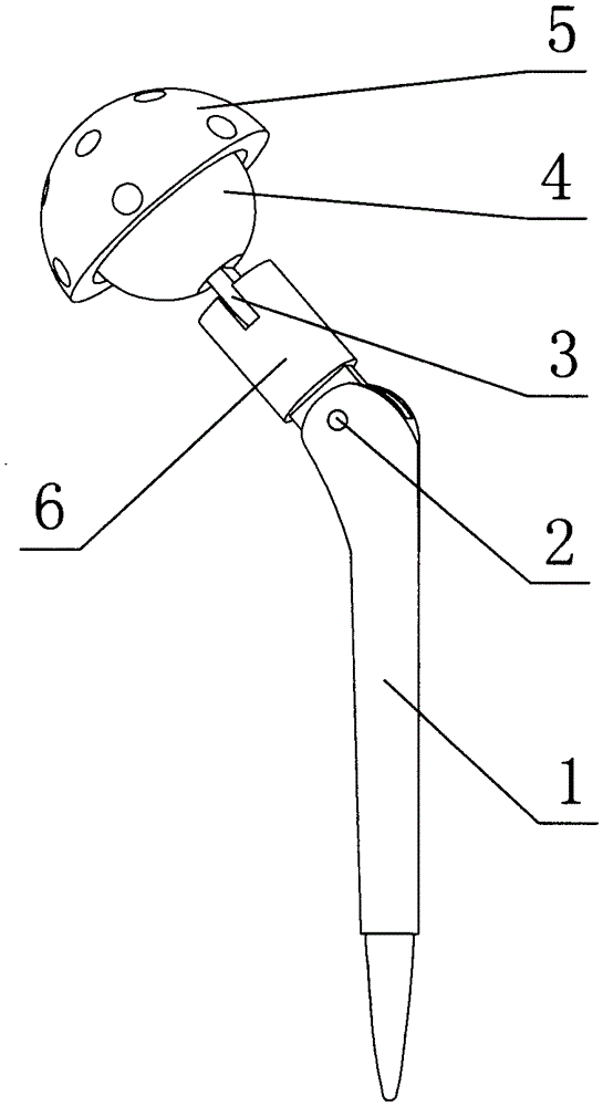
[0013] Example 1: Such as figure 1 As shown, this segmented adjustable artificial hip joint prosthesis includes a handle body 1 that can be inserted into the femoral medullary cavity. The handle body 1 extends above the side, and the axis of the extension end 6 and the handle body The angle between the axes of 1 is 110°~140°. The upper end of the extension 6 is connected to a spherical body 4 that matches the acetabulum. The handle 1 is an integrated structure, and the upper end of the extension 6 is between the spherical body 4 Twisted, that is, the lower end of the spherical body 4 is a falcon structure, the upper end of the extension end 6 is a slot that matches the falcon 3, and the falcon 3 is twisted with the slot, and the slot is fitted with fastening bolts. , The fastening bolts pass through the slot and the falcon 3 in sequence, and the lower end of the extension end 6 is hinged with the handle body 1. According to the patient’s imaging data, this embodiment can make p...

Embodiment 2

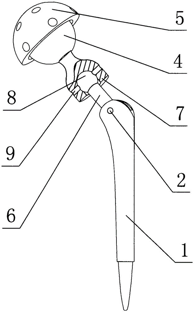
[0014] Example 2: Such as figure 2 As shown, the difference between this embodiment and embodiment 1 is that the handle body 1 is an integrated structure, the lower end 7 of the spherical body 4 is a groove-shaped structure, and the upper end of the extension end 6 is connected to the groove 7 A spherical body 8 with a matching inner diameter, the groove 7 has a hole 9 on the groove wall surface for installing fastening bolts, and the fastening bolt passes through the groove groove wall surface and the spherical body 8 in turn, and the lower end of the extension end 6 is hinged with the handle 1 even. According to the patient’s imaging data, this embodiment can make preliminary adjustments to the anteversion angle and the neck-stem angle in the sagittal and coronal positions respectively. After the femoral head is removed and placed in this embodiment routinely, the above can be adjusted appropriately according to the intraoperative situation. Two corners, and then tighten the...

Embodiment 3

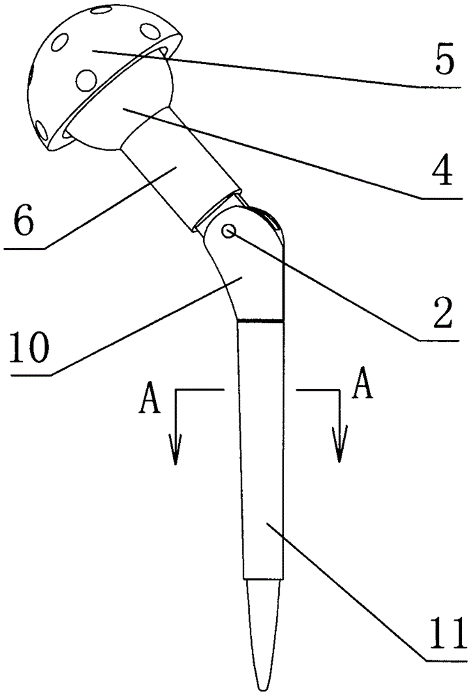
[0015] Example 3: Such as image 3 , 4 As shown, the difference between this embodiment and the first embodiment is: the upper end of the extension end 6 is fixedly connected to the spherical body 4, and the lower end of the extension end 6 is hinged with the handle body, which has a meshing plug-in structure , That is, the tooth-like structure at the lower part of the upper shank body 10 and the opening on the axis of the lower shank body 11 form a meshing plug connection. According to the patient’s imaging data, this embodiment can be used in the sagittal and coronal positions. Preliminary adjustments were made to the anteversion angle and the neck-stem angle. After the femoral head was removed and placed in this embodiment routinely, the above two angles were adjusted appropriately according to the intraoperative situation, and then the fastening bolt 2 was tightened to adjust the shank shape after the anteversion angle The bodies 10 and 11 form a tight meshing plug connectio...


PUM


Abstract

The invention discloses a sectional adjustable artificial hip joint prosthesis. The sectional adjustable artificial hip joint prosthesis comprises a handle-shaped body capable of being inserted into the femoral myelocavity, the lateral upper part of the handle-shaped body extends, an included angle between the axis of an extension end and the axis of the handle-shaped body is 110-140 degrees, the end part of the extension end is connected with a globoid matched with the acetabulum, the handle-shaped body is in an integrated structure or a meshed insertion structure, one end of the extension end is hinged with or fixedly connected with the globoid, and the other end of the extension end is hinged with the handle-shaped body. When the hip replacement operation is carried out clinically, the adjustment on the collodiaphyseal angle and the femoral neck anteversion is conveniently realized when different thighbone patients wear the hip joint prosthesis, while hip replacement is realized, dissection imbedding and fixation are realized, individual differences of the people are perfectly adapted, the hip replacement curative effect is improved, the accurate medical treatment is realized, and postoperative complications are further reduced.

Description

Technical field [0001] The present invention relates to joint prostheses. Background technique [0002] Femoral neck fractures can occur in all age groups, but it is most common in the elderly over 50 years old, and there are more women than men. Young and middle-aged femoral neck fractures are often caused by large external forces. Femoral neck fractures have high disability and mortality rates, and have become one of the main threats leading to the decline in the quality of life or death of the elderly. For patients with surgical indications, there are currently multiple hip replacements in clinical practice. This technology is becoming more mature and popular, and its 10-year excellent and good rate has exceeded 90%. After more than 70 years of development, artificial hip joint prostheses have been widely used in clinics. From the original Teflon material to the later high-strength metal-to-metal material, from the most primitive hip joint model to the later height, it confo...

Claims


Application Information

Patent Timeline
Patent Type & Authority Applications(China)
IPC IPC(8): A61F2/36
CPCA61F2/3609A61F2/3662A61F2002/3054A61F2002/365A61F2002/3652A61F2220/0091
Inventor 宇文培之冯琛郭家良张奇陈伟张英泽
Owner 陈卫
Why Eureka
Eureka Blog
Learn More