
Magnetic suspension superconductive steel rolling machine

A magnetic levitation, rolling mill technology, applied in the direction of cantilever rolling mill stand, metal rolling stand, metal rolling mill stand, etc., can solve problems such as lack of innovation in technological improvement

Inactive Publication Date: 2016-03-23
DALIAN JIAOTONG UNIVERSITY
View PDF8 Cites 0 Cited by
  • Summary
  • Abstract
  • Description
  • Claims
  • Application Information

AI Technical Summary

Problems solved by technology

However, there is a lack of innovation in technical improvement and most of the rolling mills are original rolling mill equipment, which has many shortcomings

Method used


Image

  • Magnetic suspension superconductive steel rolling machine
  • Magnetic suspension superconductive steel rolling machine
  • Magnetic suspension superconductive steel rolling machine

Examples


Embodiment Construction

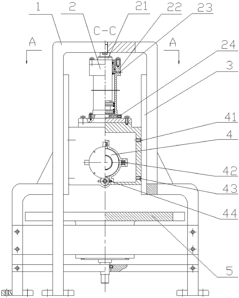
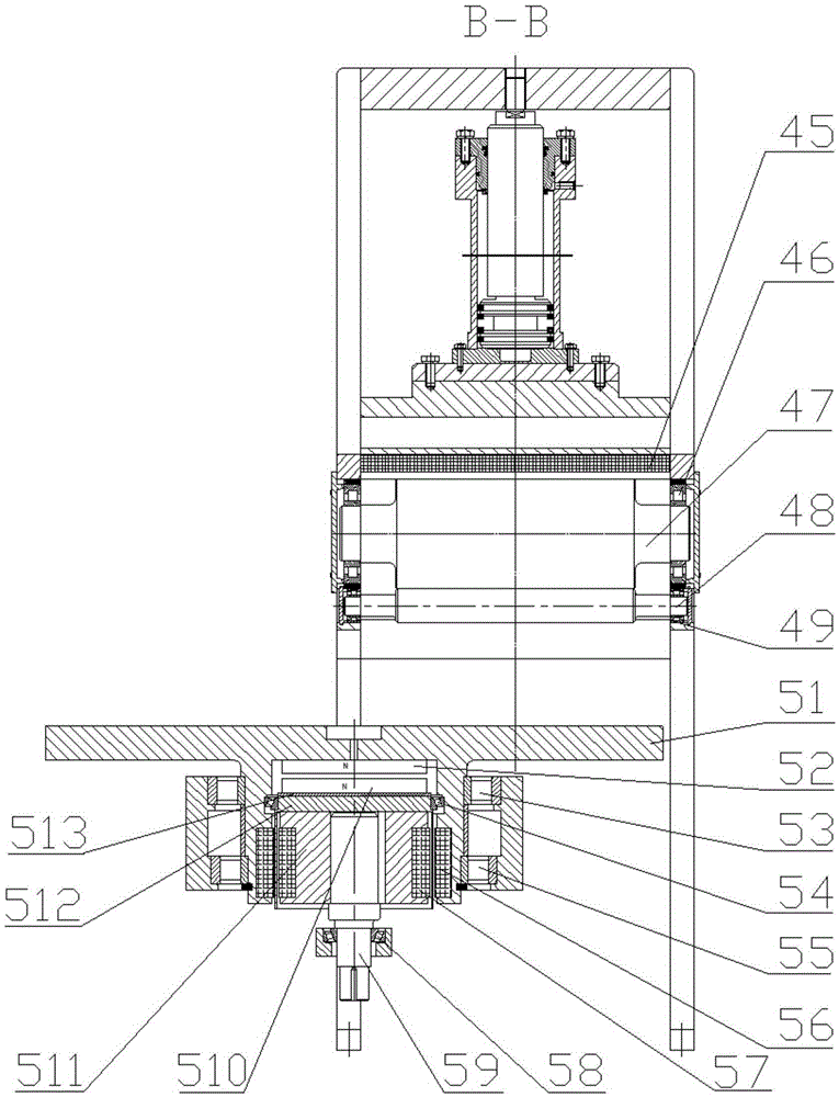
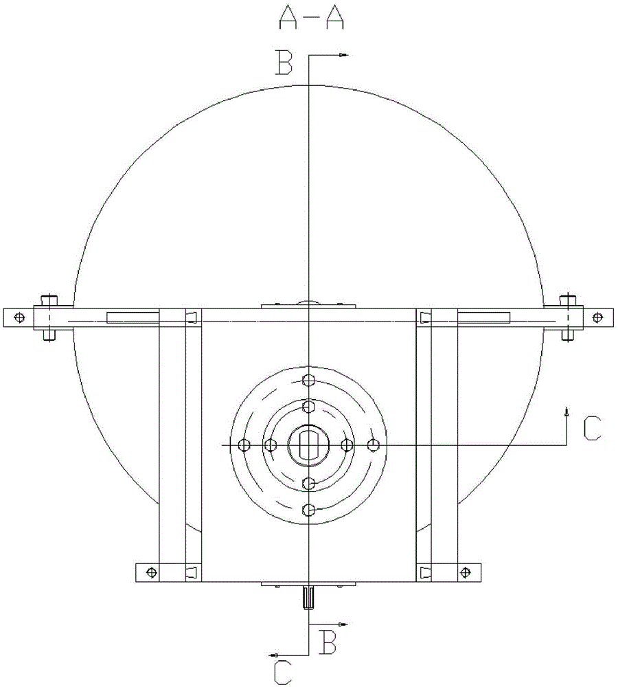
[0019] like figure 1 , figure 2 , image 3 , Figure 4 Shown 1, a kind of magnetic levitation superconducting rolling mill, comprises frame 1, hydraulic cylinder 2, guide rail 3, upper rolling mechanism 4, magnetic levitation rolling platform 5, described hydraulic cylinder 2 is composed of piston 21, cylinder block 22, It is composed of retracting oil inlet 23 and rolling oil inlet 24, which are connected to the upper part of frame 1 by thread through piston 21, cylinder body 22 is connected with upper rolling mechanism 4, and oil is fed into rolling oil inlet 24 to push hydraulic cylinder 2 to drive The upper rolling mechanism 4 presses the steel plate to be rolled along the guide rail 3, returns to the oil inlet 23 to feed oil, and pushes the hydraulic cylinder 2 to drive the upper rolling mechanism 4 to retreat from the rolled steel plate along the guide rail 3; the symmetrical guide rail 3 is fixed on the frame 1 on both sides; it is characterized in that the upper ro...


PUM


Abstract

The invention discloses a magnetic suspension superconductive steel rolling machine. A piston is connected with a frame through a thread. A cylinder body is connected with an upper rolling and pressing mechanism. The oil pressure pushes the upper rolling and pressing mechanism to move forwards and backwards along guide rails fixed to the two sides of the frame. Cooling is conducted through liquid nitrogen. The central line of a supporting roller and the central line of a working roller are kept parallel by adjusting the magnetic force of a permanent magnet. A steel plate to be rolled and pressed is flatly placed on a magnetic suspension rolling and pressing platform in the width direction of the working roller. The rotary central line of the rolling and pressing platform intersects with the central line of the working roller. The rolling and pressing platform supports the steel plate to be rolled and pressed and squeezes the working roller. The permanent magnet is installed under the rolling and pressing platform. Permanent magnetic repulsive force is generated between the rolling and pressing platform and a powered electromagnet, so that the rolling and pressing platform bears rolling and pressing force to be suspended. An external power driving shaft drives an inner permanent magnet to rotate, and an outer permanent magnet is coupled to rotate, so that the rolling and pressing platform is driven to rotate. Friction is generated between the rolling and pressing platform and the steel plate to be rolled and pressed through the rolling and pressing force of the working roller, and the rolled steel plate is pushed to move forwards. The magnetic suspension superconductive steel rolling machine has the advantages that the roller peak, the working roller which is used for plane rolling and adjusted through magnetic force and the supporting roller are parallel, and a permanent magnetic coupler drives the rolling and pressing platform to rotate so that the rolled steel plate can be pushed.

Description

technical field [0001] The technology of the invention mainly relates to the field of steel rolling equipment, in particular to a magnetic levitation superconducting steel rolling machine. Background technique [0002] At present, the rolling mills used in steel rolling machines all use upper and lower work rolls to simultaneously roll and press steel plates. The rolling mill has structures such as lower work rolls and lower support rolls, which increases the cost of manufacturing and maintenance of the equipment, and the deformation of the upper and lower work rolls causes the plate to appear. Problems such as uneven thickness, wave bending and warping; in order to avoid these problems, some rolling mills have added backup rolls or fixed rolls on both sides of the work rolls to prevent deformation of the work rolls; but this structure also cannot avoid the work rolls The deformation, but also increased the cost of production and maintenance of the rolling mill. At the same...

Claims


Application Information

Patent Timeline
IPC IPC(8): B21B1/38B21B13/00B21B31/16
CPCB21B1/38B21B13/005B21B31/16B21B2001/386
Inventor 邵万珍吴岳吴玉凯李邵颖孔奕人王开晶
Owner DALIAN JIAOTONG UNIVERSITY
Learn More