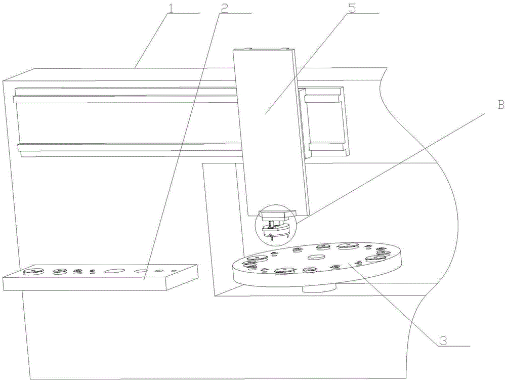
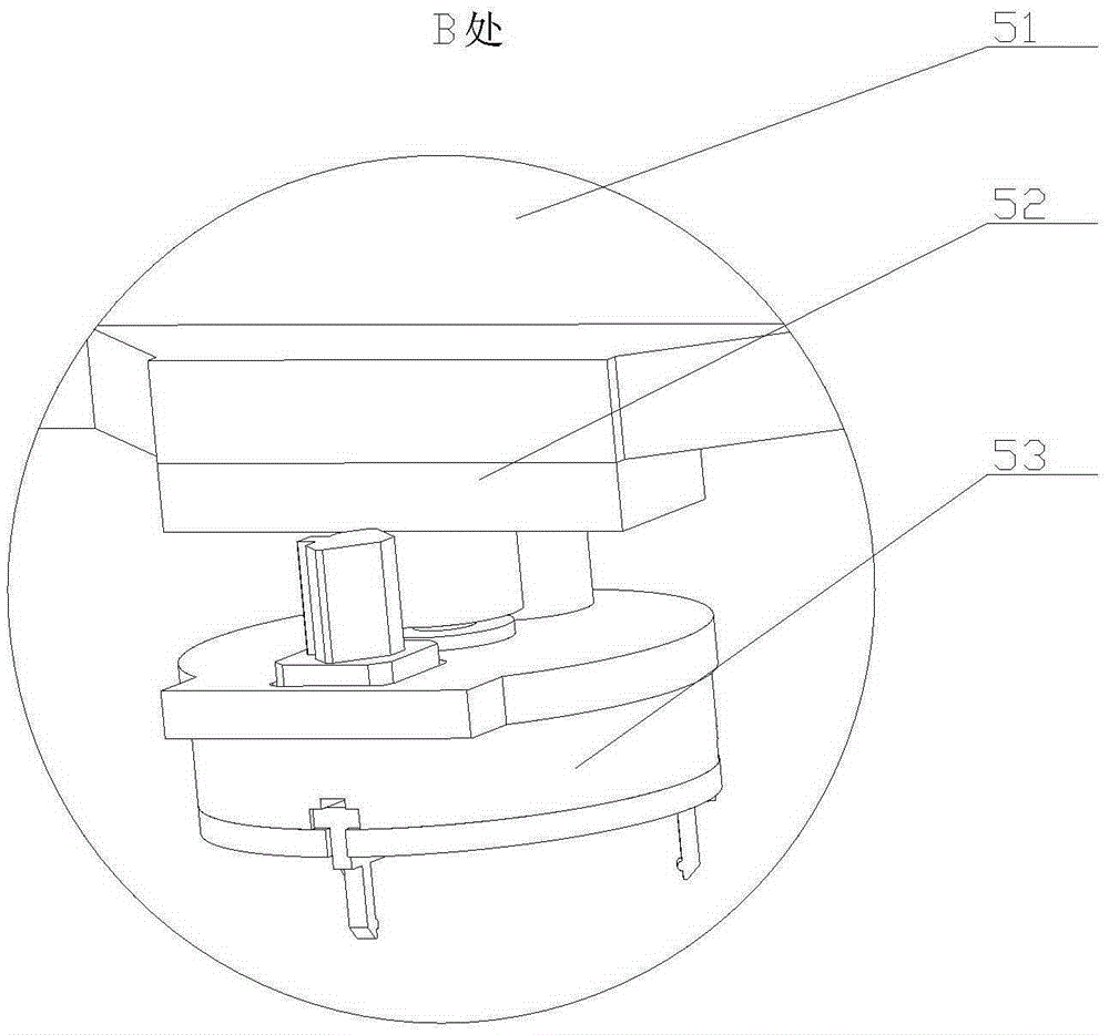
Die replacing device for numerical control turret punch press

A technology of CNC turret punch press and rotary drive device, which is applied in metal processing equipment, forming tools, manufacturing tools, etc., can solve the problems of relative motion error and large difference between the turntable and the gripper jaw, and achieve good stability and large stroke range , Efficient grasping or releasing effect

Active Publication Date: 2016-03-23
江苏扬力数控机床有限公司
View PDF6 Cites 8 Cited by
  • Summary
  • Abstract
  • Description
  • Claims
  • Application Information

AI Technical Summary

Problems solved by technology

[0003] At present, on the one hand, in order to ensure the diversity of processing, there are usually more than two external dimensions of the mold in each mold position, and some even have great differences; on the other hand, there is usually a certain error in the relative movement between the turntable and the jaws.

Method used


Image

  • Die replacing device for numerical control turret punch press
  • Die replacing device for numerical control turret punch press
  • Die replacing device for numerical control turret punch press

Examples


Embodiment 1

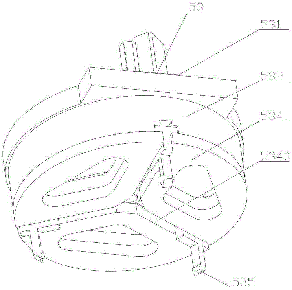
[0037]Embodiment 1: The rotary drive device 536 includes a rotary cylinder 5361 with a power shaft, a pinion gear 5362, a large gear 5363, a limit cylinder 5364 with a drive shaft, and a limit block 5365. The rotary cylinder 5361 is fixedly connected to a fixed On the seat 531, and its power shaft extends into the guide sleeve 532, the pinion 5362 is sleeved on the power shaft of the rotary cylinder 5361, the big gear 5363 is fixedly connected to the cam disc 533, and is connected with the pinion 5362 Mesh with each other, the large gear 5363 and the cam disc 533 are coaxial; in this way, the small gear can be driven by rotating the cylinder, and then the camshaft is driven to rotate through the large gear, thereby finally driving the jaws to perform linear displacement;

[0038] At the same time, because the rotary cylinder runs fast, but its running accuracy is poor, and the running volume is difficult to control, a mechanism for limiting the rotation angle of the cam disc is...

Embodiment 2

[0042] Embodiment 2: the rotary driving device includes a servo motor with an output shaft, a pinion and a bull gear, the servo motor is fixedly connected to the fixed seat, and its output shaft extends into the guide sleeve, and the pinion sleeve Connected to the output shaft of the servo motor, the large gear is fixedly connected to the cam plate and meshed with the pinion, and the large gear and the cam plate are coaxial. Since the servo motor has the characteristics of high running precision and high price, the rotation angle of the cam disc can be precisely controlled by directly sending a signal from the control center during use, that is, the displacement of the gripper jaw can be precisely controlled.

[0043] Let any point on the center line of the camshaft be point i, and the distance between point i and the axis center of the camshaft be R i , at this time, the force direction of the cam groove is the radial direction of the cam disc, and the included angle between ...


PUM


Abstract

The invention relates to the field of auxiliary equipment for a numerical control turret punch press, in particular to a die replacing device for the numerical control turret punch press. The die replacing device for the numerical control turret punch press is exquisite in structure, high in working efficiency and good in stability. When used, the die replacing device for the numerical control turret punch press can effectively clamp dies in various sizes and also can accurately and efficiently put the dies into die positions, and therefore rapid die replacement is achieved. When a cam disc rotates, arc-shaped cam grooves are used for driving clamping jaws to linearly move along radial sliding holes in a reciprocating mode, and therefore the dies below a guide plate can be conveniently and efficiently grabbed or released. The die replacing device for the numerical control turret punch press is high in working efficiency and good in stability. The die replacing device for the numerical control turret punch press can effectively clamp the dies of various sizes and also can accurately and efficiently put the dies into the die positions, and therefore the purpose of rapid die replacement is finally achieved.

Description

technical field [0001] The invention relates to the field of auxiliary equipment for a numerical control turret punch press, in particular to a die changing device therein. Background technique [0002] With the continuous improvement of the technical level, the automation level of the CNC turret punch press is also continuously improved. When the CNC turret punch press in the prior art is in use, the molds are usually taken out from the mold library and put into the corresponding mold positions on the turntable one by one, so that each mold can be easily hit by the striking head during use, and then Realize the final punching of the workpiece. In this way, in the above-mentioned mold pick-and-place process, there will be two links that are particularly important. One is to effectively grasp the mold; the other is to place the mold stably. [0003] At present, on the one hand, in order to ensure the diversity of processing, there are usually more than two external dimensio...

Claims


Application Information

Patent Timeline
Patent Type & Authority Applications(China)
IPC IPC(8): B21D37/14
CPCB21D37/14
Inventor 潘志华胡金龙张小卫陈龙
Owner 江苏扬力数控机床有限公司
Why Eureka
Try Eureka