Pipe expander

A pipe expander and the technology on the other side, applied in the field of pipe expanders, can solve the problems of inability to realize automatic production and automation, and achieve the effects of simple structure, space saving and production cost reduction

Inactive Publication Date: 2016-03-23
于建林
View PDF5 Cites 4 Cited by
  • Summary
  • Abstract
  • Description
  • Claims
  • Application Information

AI Technical Summary

Problems solved by technology

However, the equipment cannot realize fully automated production, at least in the links of storage, loading and blanking of pipe fittings, which have not been automated, or it is difficult to automatically connect with other links

Method used


Image

  • Pipe expander
  • Pipe expander
  • Pipe expander

Examples


Embodiment Construction

[0027] The present invention will be further explained below in conjunction with the accompanying drawings of the specification.

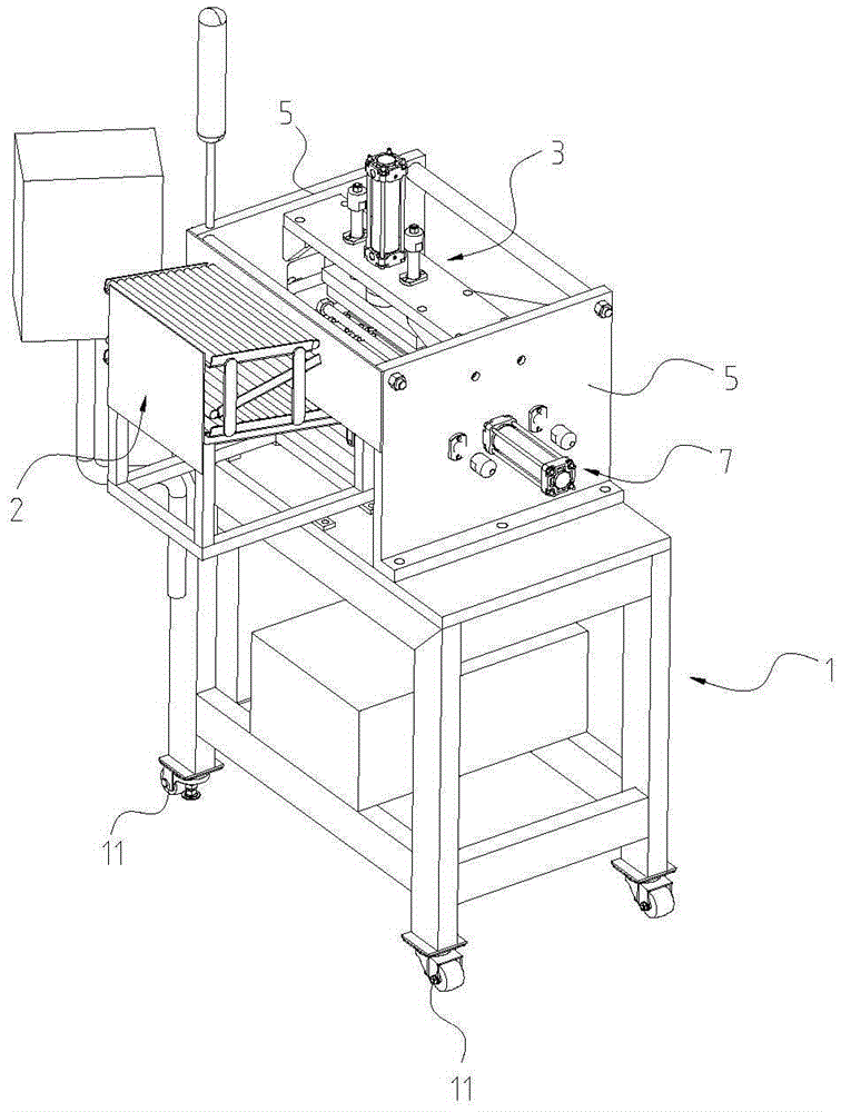
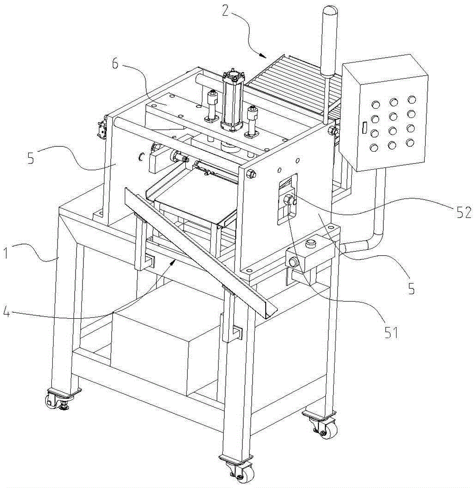
[0028] Such as Figure 1 to 3 As shown, a pipe expanding machine includes a supporting frame 1 with rollers 11 at the bottom of the supporting frame 1, and a feeding device 2, a pressing device 3, a pipe expanding device 7 and a blanking device 4 on the supporting frame 1. The pressing device 3 is located in the middle of the support frame 1, the feeding device 2 and the unloading device are respectively located on both sides of the pressing device 3 in the longitudinal direction, and the pipe expanding device 7 is distributed on two sides of the pressing device 3 in the transverse direction. side. After the steel pipe enters the pressing device 3 from the loading device 2 and is processed by the expanding device 7, it is blanked by the blanking device 4.

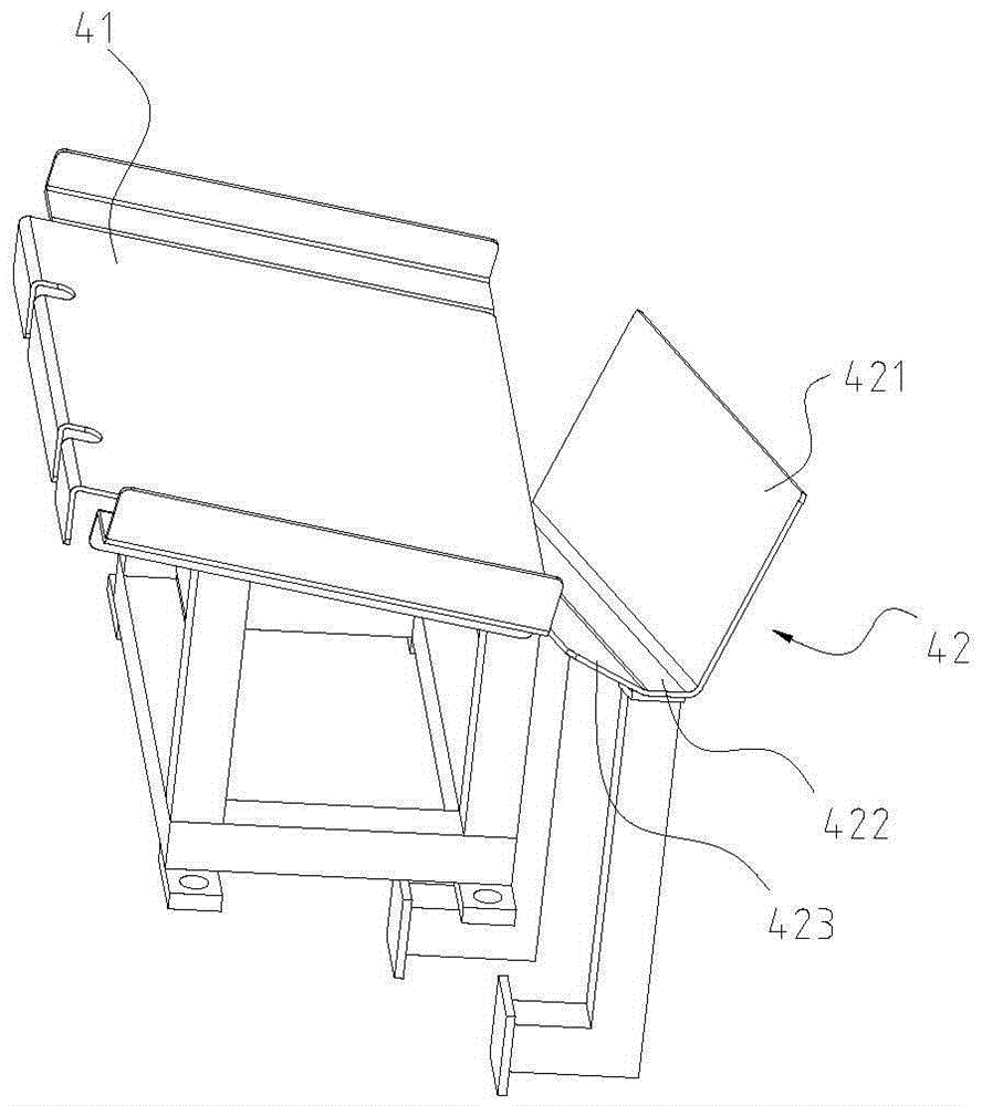
[0029] Such as Figure 4 As shown, the feeding device 2 includes a storage rack 24, two baffles...


PUM


Abstract

Provided is a pipe expander. The pipe expander comprises a feeding device, a pressing device, a pipe expanding device and a dropping device. Materials are stored and conveyed through the feeding device which is in butt joint with the pressing device. A pipe inside the feeding device is smoothly carried to the pressing device to be pressed through the pressing device. A pipe expanding process is conducted on the pressed pipe through the pipe expanding device. After the pipe expanding action is completed, pressing on the pipe is removed through the pressing device and the expanded steel pipe is carried to the dropping device to be dropped, and thus the full automatic production is completed, so that the production efficiency is high.

Description

Technical field [0001] The invention relates to pipe fitting processing equipment, in particular to a pipe expanding machine. Background technique [0002] In the prior art, the processing of the two ports of the pipe, such as pipe expansion or punching, needs to be carried out separately. First, clamp and fix the middle of the pipe, then use a pipe expansion die to expand the pipe at one end of the pipe, and then use a punching mechanism to perform the pipe expansion. The other end of the nozzle is punched to complete the operation. In order to improve the production efficiency of the pipe expander, a highly automated pipe expander has emerged, such as an automatic pipe expanding and punching device of Chinese Patent Publication No. 102009348, which includes a clamping mechanism for clamping and fixing the middle of the pipe and A pipe expanding mechanism and a punching mechanism are respectively arranged on both sides of the clamping mechanism, the clamping mechanism has a pai...

Claims


Application Information

Patent Timeline
Patent Type & Authority Applications(China)
IPC IPC(8): B21D41/02B21D43/16B21D43/00B21D45/02
CPCB21D41/02B21D43/003B21D43/006B21D43/16B21D45/02
Inventor 于建林
Owner 于建林
Why Eureka
Try Eureka