
Filling equipment for avoiding volatilization and pollution of filled liquid

A filling equipment and liquid technology, applied in the field of mechanical equipment, can solve the problems that the support structure of the foot cup is not enough to provide a stable support, affect the stability of the filling barrel, and the filling barrel is dumped, etc., to solve the problem of volatile gas pollution, rotation Smooth, environmental protection effect

Inactive Publication Date: 2016-03-23
WUXI KING CONTROL INSTR
View PDF8 Cites 3 Cited by
  • Summary
  • Abstract
  • Description
  • Claims
  • Application Information

AI Technical Summary

Problems solved by technology

After the filling is completed, the finished product is transferred to the unloading station by the conveying mechanism, and the unloading is performed by a robot or manually. The conveying mechanism in the prior art is generally supported by a foot cup. For heavy filling barrels, etc. In the filling operation, the conveying mechanism bears a large weight, and the support structure of the foot cup is not enough to provide a stable support, which will cause the conveying mechanism to vibrate during the conveying process, which will affect the stability of the filling barrel and easily cause the filling barrel to fall. There are security risks

Method used


Image

  • Filling equipment for avoiding volatilization and pollution of filled liquid
  • Filling equipment for avoiding volatilization and pollution of filled liquid
  • Filling equipment for avoiding volatilization and pollution of filled liquid

Examples


Embodiment Construction

[0018] The present invention will be further described below in conjunction with specific drawings.

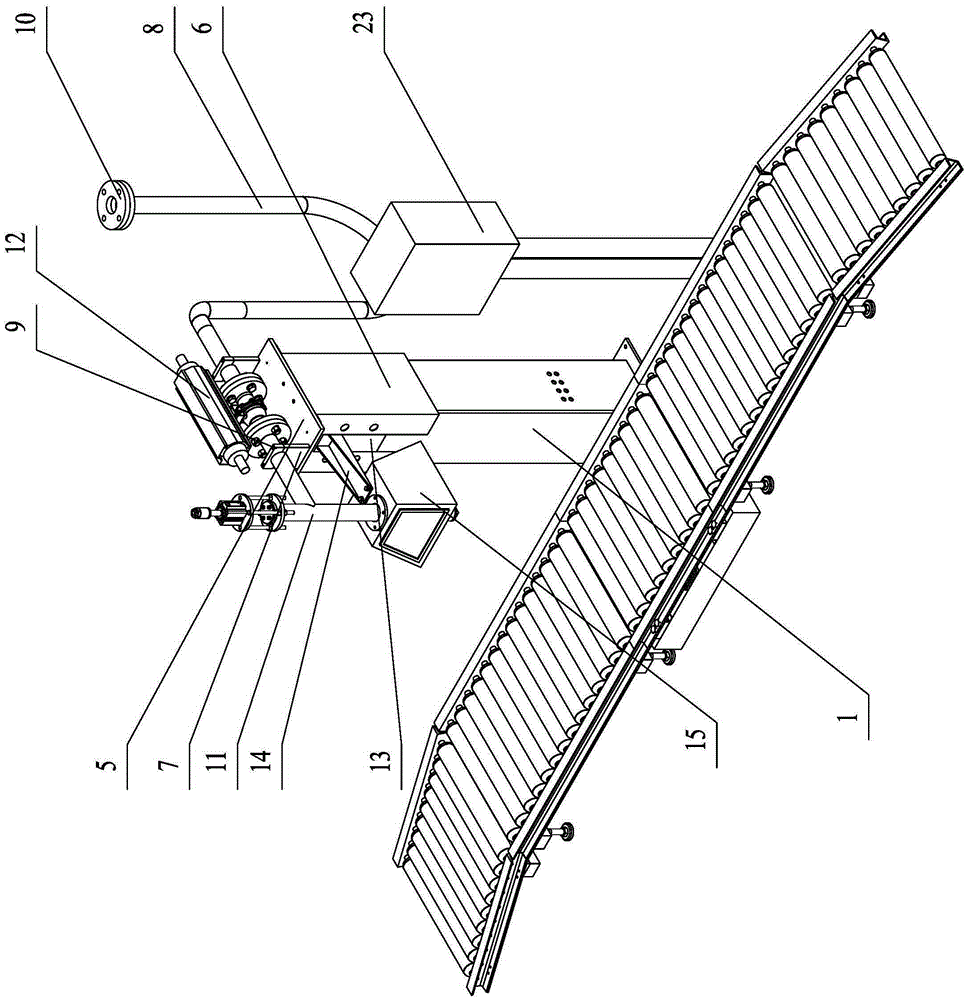
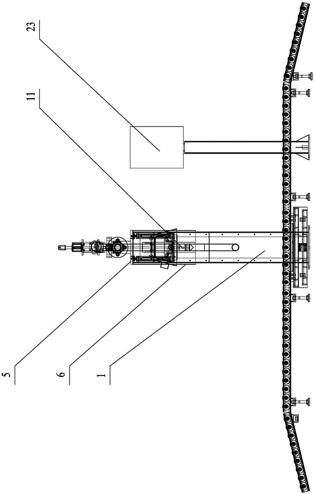
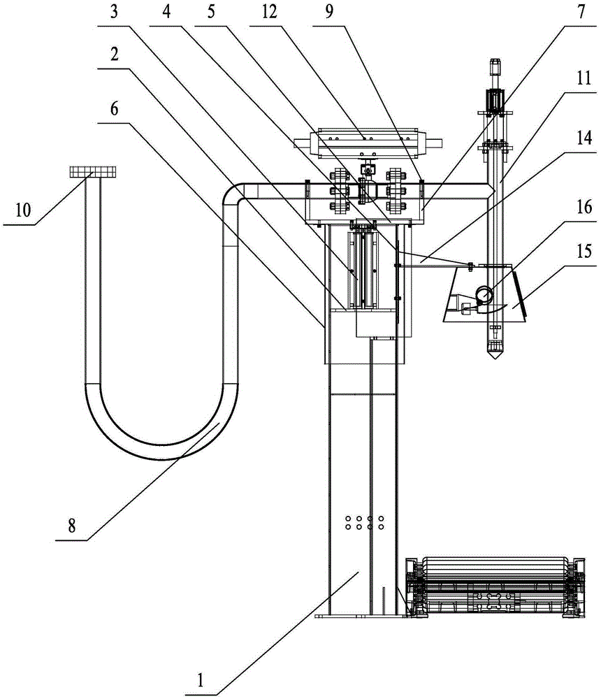
[0019] Such as Figure 1 to Figure 5 As shown: the filling equipment for preventing the volatilization and pollution of the filling liquid includes a filling frame 1, a cylinder support plate 2, a cylinder 3, a cylinder installation plate 4, a push plate 5, a casing 6, a support plate 7, and a metal hose 8. Support plate cover plate 9, flange 10, filling gun 11, two-stage ball valve 12, opening 13, gas collecting hood connecting plate 14, gas collecting hood 15, ventilation pipe connecting hole 16, first channel steel 17, The second channel steel 18, idler roller 19, fisheye joint 20, third channel steel 21, nylon universal foot cup 22, electric control cabinet 23, etc.

[0020] Such as Figure 1 ~ Figure 3 As shown, the filling equipment of the present invention includes a filling frame 1, an electric control cabinet 23 is installed on one side of the filling frame 1, a cyl...


PUM


Abstract

The invention relates to filling equipment for avoiding volatilization and pollution of a filled liquid. The filling equipment comprises a filling rack and is characterized in that an air cylinder is arranged at the top of the filling rack, a cylinder body of the air cylinder is fixed together with a mounting plate, a piston rod of the air cylinder is fixed together with a push plate, the lower surface of the push plate is connected with a housing, the push plate is provided and connected with a supporting plate on which a metal hose is placed, and the metal hose is connected with a filling gun; the mounting plate of the air cylinder is provided with a gas collecting hood connecting plate on which a gas collecting hood is arranged, a conveying mechanism is arranged under the gas collecting hood, the filling gun extends to a position below the gas collecting hood after penetrating through the top of the gas collecting hood, and ventilating pipe connecting holes are formed in two sides of the gas collecting hood; and the conveying mechanism comprises a first steel channel and a second steel channel, supporting rollers are arranged between the first steel channel and the second steel channel, third steel channels are arranged at the bottoms of the first steel channel and the second steel channel, and universal nylon cup-shaped feet are arranged at the bottoms of the third steel channels. By using the filling equipment, the pollution problem caused by by volatile gases in the filling process of a volatile liquid is solved; in addition, a supporting structure of the conveying mechanism is firm and reliable.

Description

technical field [0001] The invention relates to a filling machine, in particular to a filling device for preventing volatilization and pollution of filling liquid, and belongs to the technical field of mechanical equipment. Background technique [0002] Filling machine is a small category of products in packaging machines. It can be divided into liquid filling machine, paste filling machine, powder filling machine and granule filling machine according to the type of packaging materials. From the degree of automation of production It is divided into semi-automatic filling machine and fully automatic filling production line. [0003] In the prior art, the filling machine mainly has the following defects: [0004] (1) When the filling machine fills some volatile liquids, the liquid is easy to volatilize and pollute the production workshop and the atmospheric environment; since the current form of the gas collecting hood is mostly connected to the ventilation pipe on the upper ...

Claims


Application Information

Patent Timeline
Patent Type & Authority Applications(China)
IPC IPC(8): B67C3/30
CPCB67C3/30
Inventor 吴云水
Owner WUXI KING CONTROL INSTR
Learn More