
Coalescence type multiphase cyclone separator

A cyclone separation and flow separation technology, which is used in multi-stage series refining process treatment, petroleum industry, gas fuel, etc. Process, improve efficiency, and simplify the effect of equipment

Inactive Publication Date: 2016-03-23
淄博海润环境工程有限公司
View PDF4 Cites 6 Cited by
  • Summary
  • Abstract
  • Description
  • Claims
  • Application Information

AI Technical Summary

Problems solved by technology

[0002] The multi-phase cyclone separator is used after the oil well production fluid is pumped out and before the oil-water separation equipment. Since the oilfield production fluid treatment process at this stage is: gas-liquid separation, liquid-solid separation, liquid-liquid separation, crude oil treatment, desalination, water treatment , water injection, crude oil stabilization and other processes, the existing process structure is cumbersome and complex, requiring many types of equipment and power sources, each process requires special connection requirements, and some processes require heating and other conditions for liquid temperature. Therefore, it is necessary According to practical experience and on-site commissioning of equipment, design a separation equipment that can meet the actual needs of the separation of production fluid, reduce procedures, be efficient, save energy and cost

Method used


Image

  • Coalescence type multiphase cyclone separator
  • Coalescence type multiphase cyclone separator
  • Coalescence type multiphase cyclone separator

Examples


Embodiment Construction

[0015] The following will clearly and completely describe the technical solutions in the embodiments of the present invention with reference to the accompanying drawings in the embodiments of the present invention. Obviously, the described embodiments are only some, not all, embodiments of the present invention. Based on the embodiments of the present invention, all other embodiments obtained by persons of ordinary skill in the art without making creative efforts belong to the protection scope of the present invention.

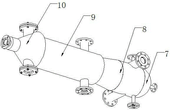
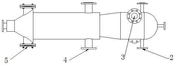
[0016] see Figure 1~3 , in an embodiment of the present invention, a coalescing multiphase cyclone separator, installed vertically, includes an oil-gas separation chamber 7, a cyclone separation chamber 8, a solid-liquid separation chamber 9 and a solid-phase sedimentation tank 10, the oil-gas The separation chamber 7, the cyclone separation chamber 8, the solid-liquid separation chamber 9 and the solid-phase sedimentation tank 10 are welded in sequence. The ...


PUM

PropertyMeasurementUnit
diameteraaaaaaaaaa

Abstract

The invention discloses a coalescence type multiphase cyclone separator which is in vertical installation. The coalescence type multiphase cyclone separator comprises an oil-gas separation cavity, a cyclone separating cavity, a solid-liquid separation cavity and a solid phase sedimentation tank. The oil-gas separation cavity, the cyclone separating cavity, the solid-liquid separation cavity and the solid phase sedimentation tank are sequentially welded. The oil-gas separation cavity is provided with a natural gas outlet and oil outlets. The natural gas outlet is arranged at the front end of the oil-gas separation cavity, the number of the oil outlets is two, the cyclone separating cavity is provided with produced liquid inlets, and the number of the produced liquid inlets is two. The solid-liquid separation cavity is provided with two water outlets, each part of mixed liquid is separated through centrifugation, separated oil and gas flow into the oil-gas separation cavity and then are discharged through the natural gas outlet and the oil outlets, separated solid and water enter the solid-liquid separation cavity, water obtained after solid phase and water phase separation is discharged timely out of the water outlets, and the solid phase is stored in the solid phase sedimentation tank to be discharged in a timed mode. Various used processes are greatly reduced, equipment is simplified, the efficiency is improved, energy is saved, and the cost is reduced.

Description

technical field [0001] The invention relates to the treatment of oil well production fluid in the field of oil fields, in particular to a coalescence multiphase cyclone separator. Background technique [0002] The multi-phase cyclone separator is used after the oil well production fluid is pumped out and before the oil-water separation equipment. Since the oilfield production fluid treatment process at this stage is: gas-liquid separation, liquid-solid separation, liquid-liquid separation, crude oil treatment, desalination, water treatment , water injection, crude oil stabilization and other processes, the existing process structure is cumbersome and complex, requiring many types of equipment and power sources, each process requires special connection requirements, and some processes require heating and other conditions for liquid temperature. Therefore, it is necessary According to practical experience and on-site commissioning of equipment, design a separation equipment th...

Claims


Application Information

Patent Timeline
Patent Type & Authority Applications(China)
IPC IPC(8): C10G53/02C10L3/10
CPCC10G53/02C10G2300/1033C10L3/10
Inventor 荆海乐张信领
Owner 淄博海润环境工程有限公司
Learn More