
Table rack for sewing machine

A sewing machine and trigger technology, applied in sewing machine components, sewing equipment, textiles and papermaking, etc., can solve the problems of unsmooth push and pull of drawer boxes, cumbersome installation, no installation position indication, etc., to reduce installation time and labor intensity, avoid Push-pull is not smooth, the connection is reliable

Inactive Publication Date: 2016-03-23
JACK SEWING MASCH CO LTD
View PDF5 Cites 4 Cited by
  • Summary
  • Abstract
  • Description
  • Claims
  • Application Information

AI Technical Summary

Problems solved by technology

[0002] There are many parts in the installation of the table frame of the existing sewing machine, and the installation requires a large number of bolt components, which requires a lot of time and labor
The connection between the upper and lower sections of the rack needs to be fixed by two rack fixing plates and several sets of bolt assemblies, and the installation is cumbersome
The installation of the platen and the governor and the frame is fixed by wood screws, but the existing platen has no installation position indication, and the user can only determine the position by experience. During the installation process, it is necessary to repeatedly determine the position with the help of tools. Confirm that the distance between the left and right parts of the rack is appropriate to ensure that the parts between the left and right parts can be installed smoothly
The pedal crosspiece is usually installed under the frame base, and the fixing bolt assembly is screwed under the base, which makes installation and secondary reinforcement difficult
The drawer box on the back of the table needs to be manually installed with drawer guide rails, and it is easy to cause the problem that the drawer box cannot be pushed and pulled smoothly due to poor installation of the guide rails

Method used


Image

  • Table rack for sewing machine
  • Table rack for sewing machine
  • Table rack for sewing machine

Examples


Embodiment Construction

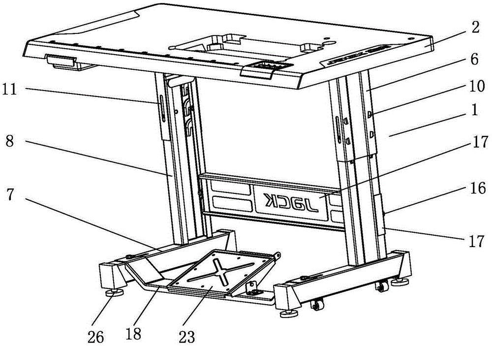
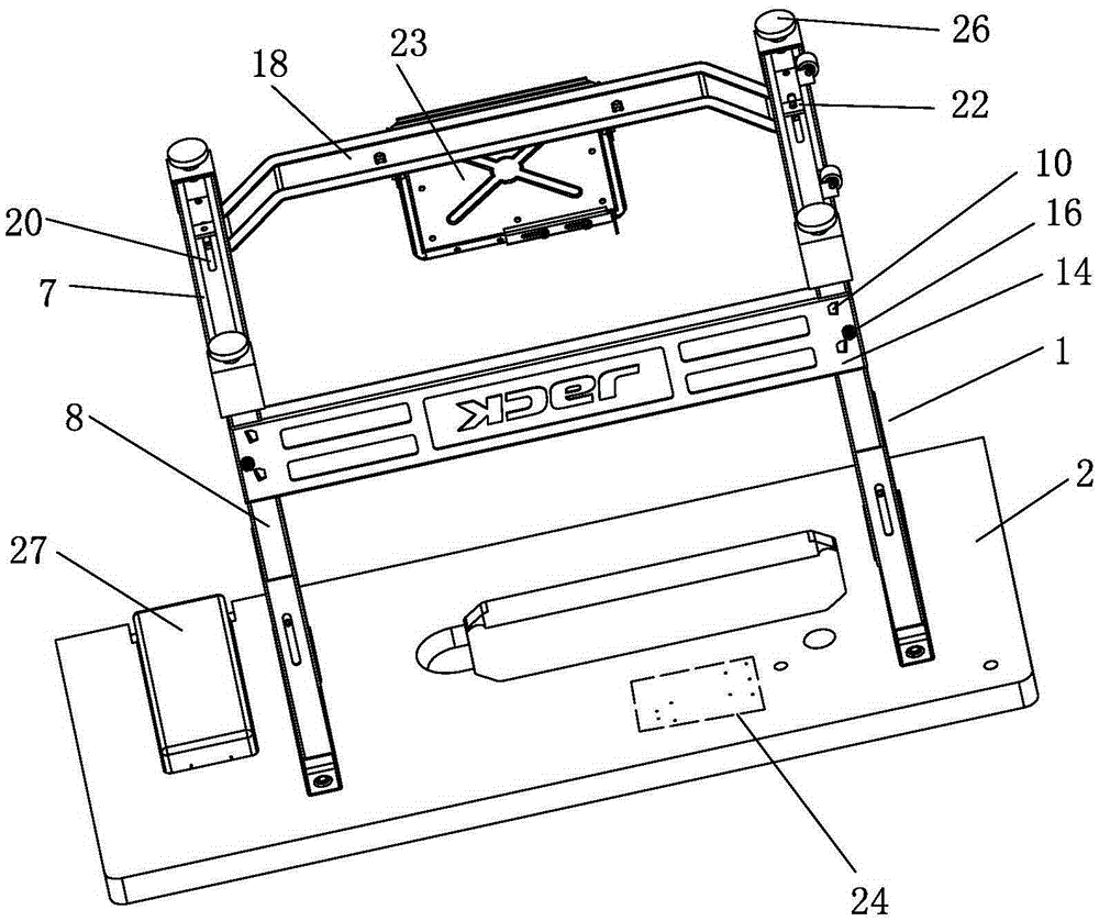
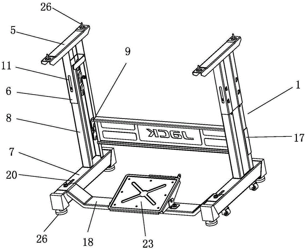
[0029] The present invention will be further described below with specific embodiment, see figure 1 -8:

[0030] A kind of sewing machine platen frame, comprises frame 1 and the platen 2 that is arranged on the frame, described frame 1 comprises the left frame and the right frame that left and right intervals are arranged, left frame, right frame The frame is composed of an upper section 3 and a lower section 4 respectively, the upper section 3 includes an upper section horizontal part 5 and an upper section vertical section 6, the lower section 4 includes a lower section horizontal section 7 and a lower section vertical section 8, and the lower section The vertical part 8 is provided with more than one set of card slots 9. In this embodiment, there are two groups arranged at intervals up and down. Each group includes two card slots 9. The number of sets of card slots can also be adjusted according to the actual situation. The upper vertical part 6 is provided with a hook 10 ...


PUM


Abstract

The invention belongs to the technical field of sewing machine fittings, and particularly relates to a table rack for a sewing machine. The table rack comprises a rack and a table arranged on the rack, wherein the rack comprises a left rack and a right rack which are arranged at an interval left and right, each of the left rack and the right rack comprises an upper section and a lower section, each upper section comprises an upper section horizontal part and an upper section vertical part, each lower section comprises a lower section horizontal part and a lower section vertical part, one or more groups of clamping grooves are formed in each lower section horizontal part, clamping hooks capable of being clamped in the clamping grooves are arranged on each upper section horizontal part, each upper section vertical part sleeves the corresponding lower section vertical part, and is connected into the clamping grooves of the corresponding lower section vertical part through the clamping hooks in a clamping manner, and the upper section horizontal part is connected with the table. According to the table rack, a user can conveniently adjust and mount pedal crosspieces, so that the mounting time and the labor intensity of the use are reduced.

Description

Technical field: [0001] The invention belongs to the technical field of sewing machine accessories, in particular to a sewing machine table frame. Background technique: [0002] There are many parts in the installation of the table frame of the existing sewing machine, and the problem that a large number of bolt assemblies are required for the installation requires a lot of time and labor. The connection between the upper and lower sections of the rack needs to be fixed by two rack fixing plates and several sets of bolt assemblies, and the installation is cumbersome. The installation of the platen and the governor and the frame is fixed by wood screws, but the existing platen has no installation position indication, and the user can only determine the position by experience. During the installation process, it is necessary to use tools to repeatedly determine the position. Confirm that the distance between the left and right parts of the rack is appropriate to ensure that t...

Claims


Application Information

Patent Timeline
Patent Type & Authority Applications(China)
IPC IPC(8): D05B75/00
CPCD05B75/00
Inventor 吴克宏潘建国洪志敏
Owner JACK SEWING MASCH CO LTD
Learn More