
Mold support auxiliary tool

A technology for auxiliary tooling and formwork, which is applied in the joints of formwork/formwork/work frame, on-site preparation of building components, construction, etc. It can solve the problems of weak binding force and easy bending of formwork, and achieve uniform thickness of protective layer Effect

Inactive Publication Date: 2016-03-23
STATE GRID BEIJING ELECTRIC POWER +1
View PDF12 Cites 1 Cited by
  • Summary
  • Abstract
  • Description
  • Claims
  • Application Information

AI Technical Summary

Problems solved by technology

[0003] The main purpose of the present invention is to provide a formwork auxiliary tooling to solve the problem of weak binding force and easy bending of formwork in the prior art

Method used


Image

  • Mold support auxiliary tool
  • Mold support auxiliary tool
  • Mold support auxiliary tool

Examples


Embodiment Construction

[0023] It should be noted that, in the case of no conflict, the embodiments of the present invention and the features in the embodiments can be combined with each other. The present invention will be described in detail below with reference to the accompanying drawings and examples.

[0024] In order to enable those skilled in the art to better understand the solutions of the present invention, the following will clearly and completely describe the technical solutions in the embodiments of the present invention in conjunction with the drawings in the embodiments of the present invention. Obviously, the described embodiments are only It is an embodiment of a part of the present invention, but not all embodiments. Based on the embodiments of the present invention, all other embodiments obtained by persons of ordinary skill in the art without making creative efforts shall fall within the protection scope of the present invention.

[0025] It should be noted that the terms "first...


PUM


Abstract

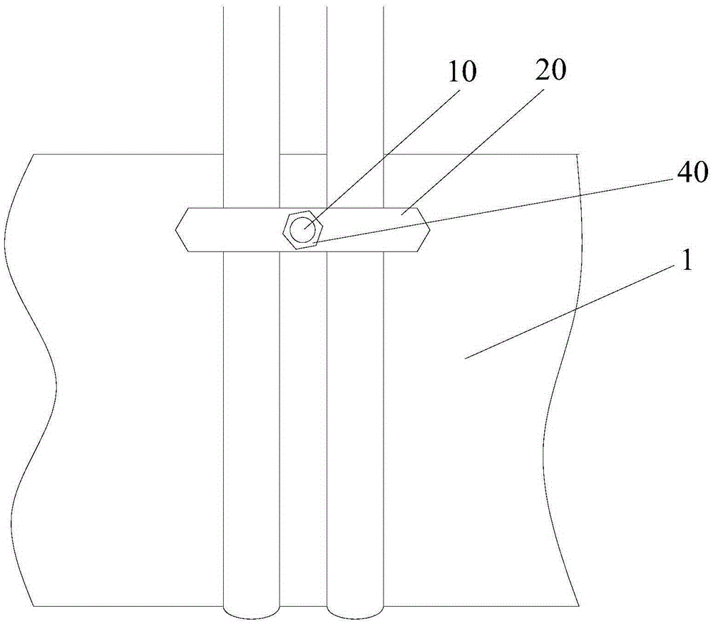
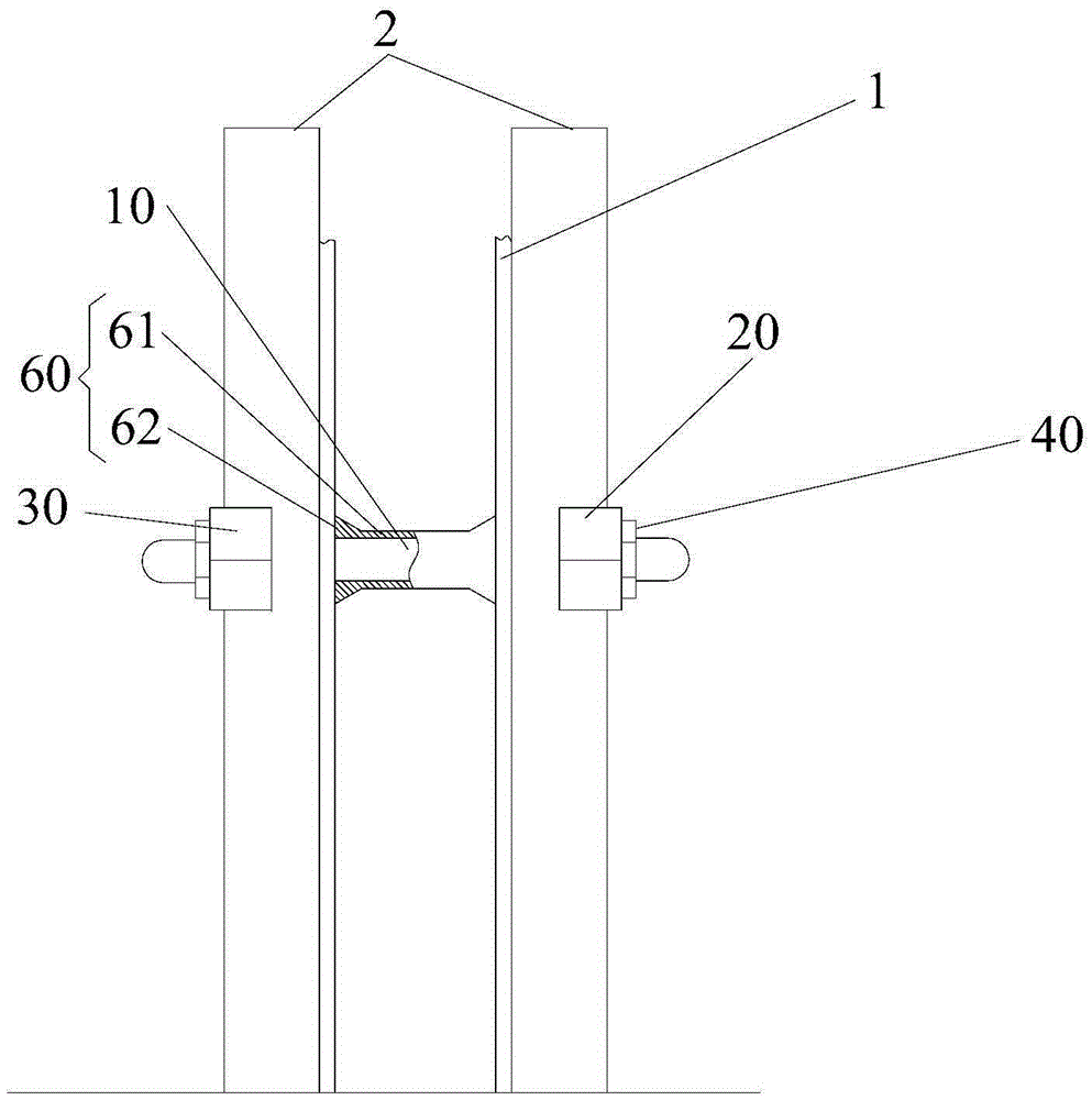
The invention provides a mold support auxiliary tool. The mold support auxiliary tool comprises a connecting rod, a first stop member and a second stop member, wherein the connecting rod is used for penetrating through two templates, and two ends of the connecting rod protrude out of the two templates. The first stop member is connected with one end of the connecting rod and is used for propping against one template, the second stop member is connected with other end of the connecting rod and is used for propping against the other template. In use, the mold support auxiliary tool is arranged on a template to fix the part with weak binding force of rebar. When concrete is poured between the two templates, even if the concrete reaches the upper part of the template and extrudes the templates to bend towards the outside, the first stop member and the second stop member can provide bonding force for the two templates, so as to avoid bending of the two templates towards the outside, and thus ensuring uniform thickness of a protection layer during pouring.

Description

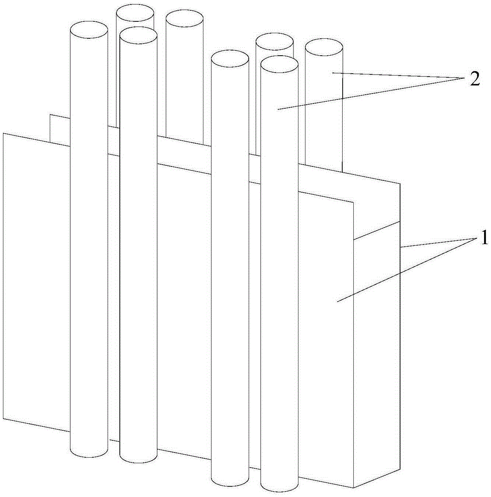
technical field [0001] The invention relates to the technical field of construction, in particular to an auxiliary formwork support tool. Background technique [0002] At present, in the process of substation civil engineering construction, reinforced concrete pouring work accounts for more than 95% of the entire civil engineering volume. The formwork process is an extremely important link in the pouring work. The quality of the formwork process directly affects the quality of concrete pouring and directly determines the quality of the entire substation project. In concrete pouring, the control of pouring density, pouring smoothness and pouring protective layer thickness are three important indicators to measure the quality of concrete pouring. Such as figure 1 As shown, in the traditional concrete pouring work, the control of the thickness and flatness of the protective layer is realized by the way of fixing the steel bar 2 and matching the formwork 1 to limit the positio...

Claims


Application Information

Patent Timeline
Patent Type & Authority Applications(China)
IPC IPC(8): E04G17/00
CPCE04G17/00
Inventor 杨根生宋振辉聂杰良贺明宋鑫
Owner STATE GRID BEIJING ELECTRIC POWER
Learn More