Splicing structure used for combined type tunnel lining, culvert or comprehensive pipe gallery

A comprehensive pipe gallery and combined technology, applied in the direction of tunnel lining, tunnel, shaft lining, etc., can solve the problems of affecting the appearance, reducing the passage space of the pipeline, collision or scratching, etc., to increase the internal passage space and the amount of engineering excavation The effect of reduction and reduction of cross-sectional area

Inactive Publication Date: 2016-03-23
NANJING LIANZHONG CONSTR ENG TECH
15 Cites 2 Cited by

AI-Extracted Technical Summary

Problems solved by technology

The support structure of this patent application is mainly used in tunnel lining projects. When the support structure is spliced ​​along the axial direction, its side flanges and their connecting bolts are exposed on the inner side of the tunnel, which is easy to collide with or scratch the internal passing vehicles. The damage to the vehicle and the supporting structure is relatively large; at the same time, the s...

Method used

Construction method: the present invention is used for the splicing structure of combined tunnel lining, and the focus is that installers can assemble the unit plates on the inside of the pipeline to solve the problem that there is no construction space outside the tunnel or trenchless culvert pipeline. After the construction starts, the surrounding rock 115 is excavated according to the section size of the tunnel lining. The size of the excavation surface is slightly larger than that of the lining section. After the initial setting of the concrete, the lining structure can be organized and assembled. The installer assembles the unit plates 101 in the circumferential direction and the axial direction through the splicing operation...

Abstract

The invention discloses a splicing structure used for a combined type tunnel lining, a culvert or a comprehensive pipe gallery. Unit plates are spliced into pipe joints in a circumferential direction; the pipe joints are axially spliced to form the tunnel lining, the culvert or the comprehensive pipe gallery, wherein when the pipe joints are axially spliced, contact end parts of adjacent unit plates are provided with folding sides folded to the outer sides of the pipe joints or hollow cavity structures with cross sections peripherally closed; and the contact surfaces of the adjacent folding sides or the hollow cavity structures are spliced connecting surfaces. The splicing structure is not exposed to the inner part of the tunnel or the culvert, does not affect passing vehicles therein and avoids collision or scratches; and meanwhile, the spliced part of the tunnel or the culvert inner wall is smooth and attractive, the inner passing space is increased, the section area is reduced, the engineering excavated volume is reduced, and the construction period is shortened.

Application Domain

Artificial islandsGround-work +4

Technology Topic

Image

  • Splicing structure used for combined type tunnel lining, culvert or comprehensive pipe gallery
  • Splicing structure used for combined type tunnel lining, culvert or comprehensive pipe gallery
  • Splicing structure used for combined type tunnel lining, culvert or comprehensive pipe gallery

Examples

  • Experimental program(1)

Example Embodiment

[0021] The technical scheme of the present invention will be further described below in conjunction with the drawings.
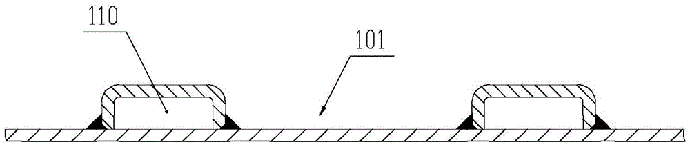
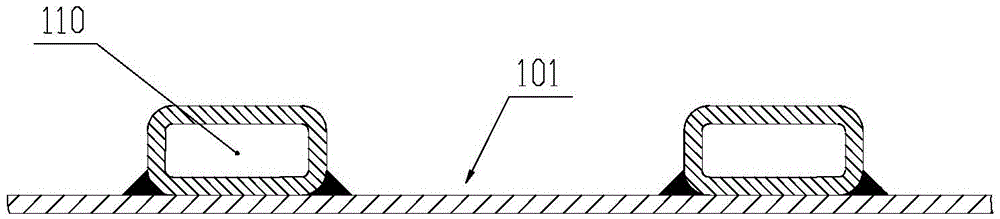
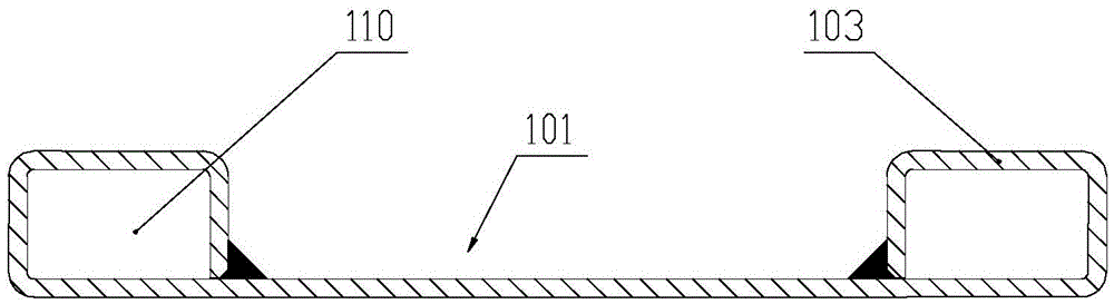
[0022] The splicing structure of the present invention includes the unit plates 101 being assembled in the circumferential direction to form a pipe section 102, which is spliced ​​along the axial direction to form a tunnel lining or culvert 100; wherein, when the pipe section 102 is spliced ​​in the axial direction, adjacent unit plates The contact ends of the sheet 101 each have a folded edge 104 or a hollow cavity structure 110 that is turned to the outside of the pipe section. The cross section of the hollow cavity structure 110 is closed and the adjacent folded edge 104 or the hollow cavity structure 110 is in contact The surface is the splicing connection surface, such as Picture 9 , 10 Shown. Preferably, the contact surface can be connected by a workpiece such as a bolt. Since the hemming or hollow cavity structure is located outside of the tunnel, culvert or integrated pipe gallery, a splicing operation hole 111 is opened on the unit plate near the splicing connection surface, so that tools can be inserted from the splicing operation hole 111 for tightening bolts After the work is completed, an operation hole cover 113 can be correspondingly provided on the assembling operation hole 111.
[0023] The adjacent unit plates 101 assembled in the circumferential direction can be welded or spliced ​​through the connecting plate 112, and the unit plates near the connecting plate 112 also have splicing operation holes 111. Such as Figure 7 , 8 As shown, the splicing operation holes are distributed on the four sides of the unit plate 101.
[0024] The unit plate 101 of the present invention may be an arc-shaped piece, with a hollow cavity structure 110 with a closed cross section and a periphery on the outside and/or inside. The hollow cavity structure 110 can have a certain length, and the two ends can be penetrated or closed at one end and open at one end. Compared with the hollow cavity structure of the open cross section, the hollow cavity structure of the closed cross section has higher torsional rigidity and stronger ability of resisting vertical instability.
[0025] The above hollow cavity structure 110 can be separately buckled on the unit plate 101, such as Figure 1(a) , 1(b) , 1(o)-1(r). The unit plate is composed of a metal plate 106, and the hollow cavity structure 110 can be formed by bending the metal plate 106 itself. The bent cross-sectional shape can be rectangular, circular, etc., and the hollow cavity structure 103 and the unit plate The gap weld formed between the sheets 101, such as Figure 1(c) , 1(d) , As shown in 1(e). The metal plate 106 can also be bent to form the shape of the protrusion 103, and the hollow cavity structure 110 can be formed by combining a plate or tube with the protrusion 103, such as Figure 1(f)-1(n) As shown, the shape of the cavity formed by bending can be trough, arc, semicircle, etc., and the plate used can be steel plate, channel steel, C-shaped steel, arc steel plate, etc. The above-mentioned unit plate 101 can also be formed by splicing a metal plate 106 and a metal tube 107, such as Figure 2(a)-2(e) As shown; or by the side-by-side splicing of metal pipes 107, the cross-section of which is a chain structure, such Figure 3(a) , 3(b) , 3(c); or the corrugated plates 108 are interlocked with each other to form a unit plate with a hollow cavity structure 110, as shown in Figure 4(a); or by C-shaped steel, channel steel, I-beam, The arc steel, angle steel or corrugated plate is buckled with the flat plate 109 to form a unit plate with a hollow cavity structure 110, as shown in FIG. 4(b). In the above, bending a flat plate into a plate with an arc, corrugated, groove, etc. shape can increase the vertical bearing capacity of the unit plate. Wherein, when the pipe sections 102 are spliced ​​in the axial direction, the contact ends of the adjacent unit plates 101 all have a metal tube 107 or a hollow cavity structure 110 bent to the outside of the pipe section, and adjacent metal pipes 107 or hollow cavity structures The contact surface of 110 is the splicing connection surface.
[0026] The metal tube 107 or the hollow cavity structure 110 of the present invention can be filled with concrete 105. When filling, the metal tube 107 or the hollow cavity structure 110 on the unit plate can be poured with concrete 105 and then assembled; or the adjacent unit The metal pipes 107 or the hollow cavity structure 110 on the slabs are connected end to end to form a continuous hollow cavity structure, assembled to form pipe sections and then poured as a whole, correspondingly, concrete pouring holes and concrete overflow holes are opened on the top of the pipe sections. The invention utilizes the superior pressure-bearing capacity of concrete and the surrounding effect of steel pipes on the concrete, can delay the generation and expansion of concrete cracks in the hollow cavity structure to the greatest extent, and further enhance the vertical pressure-bearing capacity of the pipe gallery.
[0027] Construction method: The present invention is used in the splicing structure of the combined tunnel lining. The key point is that the installer can assemble the unit plates on the inside of the pipeline to solve the problem of no construction space outside the tunnel or trenchless culvert pipeline. After the start of construction, the surrounding rock 115 is excavated according to the size of the tunnel lining section. The size of the excavation surface is slightly larger than that of the lining section. After the excavation is completed, the loose surrounding rock is removed and the early-strength concrete 116 is sprayed to stabilize the inner surface of the tunnel. After the initial setting of the concrete, the lining structure can be organized and assembled. The installer assembles the unit plates 101 in the circumferential and axial directions through the splicing operation holes 111 inside the pipeline, and the splicing operation holes 111 are sealed with the operation hole cover 113 after the assembly is completed. The concrete 105 can be poured into the concrete pouring hole on the unit plate 101 as required. When it flows out of the concrete overflow hole 117, it means that the concrete has filled the gap between the structural member and the tunnel soil layer, which can improve the strength of the overall component ,Such as Picture 11 , 12 Shown. It is also possible to insert the embedded part 114 or other components on the operating hole cover 113 according to the needs, and then block and pour the concrete 105 to further improve the strength of the overall structure, such as Figure 13 , 14 Shown.

PUM

no PUM

Description & Claims & Application Information

We can also present the details of the Description, Claims and Application information to help users get a comprehensive understanding of the technical details of the patent, such as background art, summary of invention, brief description of drawings, description of embodiments, and other original content. On the other hand, users can also determine the specific scope of protection of the technology through the list of claims; as well as understand the changes in the life cycle of the technology with the presentation of the patent timeline. Login to view more.

Similar technology patents

Classification and recommendation of technical efficacy words

  • Reduce the cross-sectional area

Electromagnetic valve

Owner:浙江中宝自控元件有限公司

Catheter

Owner:MEDTRONIC PS MEDICAL

Switchgear spout design

ActiveUS20140185193A1Reduce the cross-sectional areaSmall widthNon-enclosed substationsSwitchgear arrangementsElectrical switchingEngineering
Owner:EATON INTELLIGENT POWER LIMITED
Why Eureka
Try Eureka