Check patentability & draft patents in minutes with Patsnap Eureka AI!

Super-gravity concentration difference power generation device and method

A power generation device and super-gravity technology, which is applied in the direction of machines/engines, mechanisms for generating mechanical power, mechanical equipment, etc., can solve the problems of high-efficiency energy recovery devices such as high prices, unfavorable cycle ratios, and reduced technical and economic value of the system to achieve high Technical and economic value, simple system structure, automatic and efficient recovery effect

Active Publication Date: 2016-03-23
ZHEJIANG SCI-TECH UNIV
View PDF7 Cites 2 Cited by
  • Summary
  • Abstract
  • Description
  • Claims
  • Application Information

AI Technical Summary

Problems solved by technology

[0003] When using the principle of pressure-delayed osmosis to generate electricity, it is generally necessary to use a high-efficiency energy recovery device to recover a part of the pressure energy of the high-pressure liquid to improve system efficiency, but the high-efficiency energy recovery device is expensive, which reduces the technical and economic value of the system, which is especially unfavorable for circulation. Larger magnification system

Method used


Image

  • Super-gravity concentration difference power generation device and method

Examples


Embodiment 1

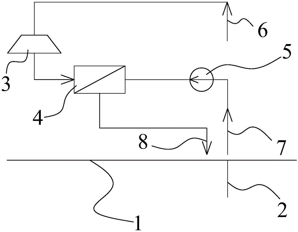
[0020] Embodiment 1, figure 1 Provided is a supergravity concentration difference power generation device and method. The supergravity concentration power generation device includes a power generation device and a pressure concentration difference work device; the power generation device is a liquid turbine 3 , and the pressure concentration difference work device is a permeator 4 .

[0021] The inlet side of the liquid turbine 3 is provided with a pure water inlet 6, and there is a pipe I connection between the inlet of the liquid turbine 3 and the pure water inlet 6. The pure water inlet 6 is connected to a pure water storage tank and other devices, and through the pure water storage tank The pure water is drawn out by other devices and imported into the liquid turbine 3; the outlet of the liquid turbine 3 is connected to the liquid inlet I of the permeator 4, and the pure water in the liquid turbine 3 is introduced into the permeator 4 through the liquid inlet; the solution...

Embodiment 1

[0032] The calculation parameters of implementation example 1 are shown in Table 1 (for 1 kg of water). The design conditions are: the radius of gyration of the system is 0.5m, the chemical energy contained in the calcium chloride solution and pure water is used for concentration difference power generation, the concentration of the concentrated calcium chloride solution is 18%, the temperature is 25°C, and the osmotic pressure is 11Mpa. When the cycle rate is 4 times (defined as the ratio of dilute solution to water), the concentration of the dilute solution obtained is 13.5%, the osmotic pressure is 8.3Mpa, the average driving pressure difference of the pressure-delayed osmotic process is 3.1Mpa, and the system speed is 2045 rpm / min, solution pump efficiency is 80%, power consumption is 0.67kJ / kg, liquid turbine efficiency is 80%, output work is 4.34kJ / kg, system net output work is 3.67kJ / kg, system exergy efficiency (defined as The ratio of the theoretical work to the net ...


PUM


Abstract

The invention discloses a super-gravity concentration difference power generation device. The super-gravity concentration difference power generation device comprises a power generation device body and a pressure concentration difference acting device. The power generation device body is a liquid turbine (3). The pressure concentration difference acting device is a permeation device (4). A pure water inlet (6) is formed in one side of an inlet of the liquid turbine (3), an outlet of the liquid turbine (3) is connected to a liquid inlet of the permeation device (4), a concentrated solution inlet (7) is formed in one side of a solution inlet of the permeation device (4), and a permeable membrane is arranged between the liquid inlet and the solution inlet of the permeation device (4). A pipeline I is arranged between the pure water inlet (6) and the inlet of the liquid turbine (3), and a pipeline II is arranged between the solution inlet and the concentrated solution inlet (7).

Description

technical field [0001] The invention relates to the technical field of power equipment, in particular to a supergravity concentration difference power generation device and method. Background technique [0002] When there is a concentration difference between the two liquids, the solvent components in the liquids have different chemical potentials, which can be used to do work theoretically. The chemical potential is small, and the principle of pressure-delayed osmosis can make fresh water seep into the high-pressure seawater side and enter the hydro turbine to generate electricity. This technology has been applied. For example, the Norwegian Statkraft company has built the world's first power station using seawater concentration energy. . [0003] When using the principle of pressure-delayed osmosis to generate electricity, it is generally necessary to use a high-efficiency energy recovery device to recover a part of the pressure energy of the high-pressure liquid to impro...

Claims


Application Information

Patent Timeline
Patent Type & Authority Applications(China)
IPC IPC(8): F03G7/00
CPCF03G7/005
Inventor 王厉
Owner ZHEJIANG SCI-TECH UNIV
Features
  • R&D
  • Intellectual Property
  • Life Sciences
  • Materials
  • Tech Scout
  • Unparalleled Data Quality
  • Higher Quality Content
  • 60% Fewer Hallucinations
Learn More