Check patentability & draft patents in minutes with Patsnap Eureka AI!

High gravity reverse osmosis solution separation device and method

A separation device and separation method technology, applied in reverse osmosis, non-polluting water treatment, seawater treatment and other directions, can solve the problem of high price of liquid energy recovery device, and achieve the effect of high technical and economic value and simple system structure

Active Publication Date: 2017-10-31
ZHEJIANG SCI-TECH UNIV
View PDF3 Cites 0 Cited by
  • Summary
  • Abstract
  • Description
  • Claims
  • Application Information

AI Technical Summary

Problems solved by technology

[0003] In reverse osmosis, the dilute solution is generally pressurized to a high pressure of Mpa level. After the water in the dilute solution permeates out through the osmotic membrane, the remaining concentrated solution still has a large liquid pressure energy, which can be recovered by a liquid energy recovery device. Recover this part of energy, improve system efficiency, and increase the technical economy of the system, but the liquid energy recovery device is expensive. For example, in seawater desalination projects, the initial investment cost of the energy recovery device accounts for 10-15% of the total investment, which makes Liquid energy recoverers are not widely used in reverse osmosis solution separation

Method used


Image

  • High gravity reverse osmosis solution separation device and method

Examples


Embodiment 1

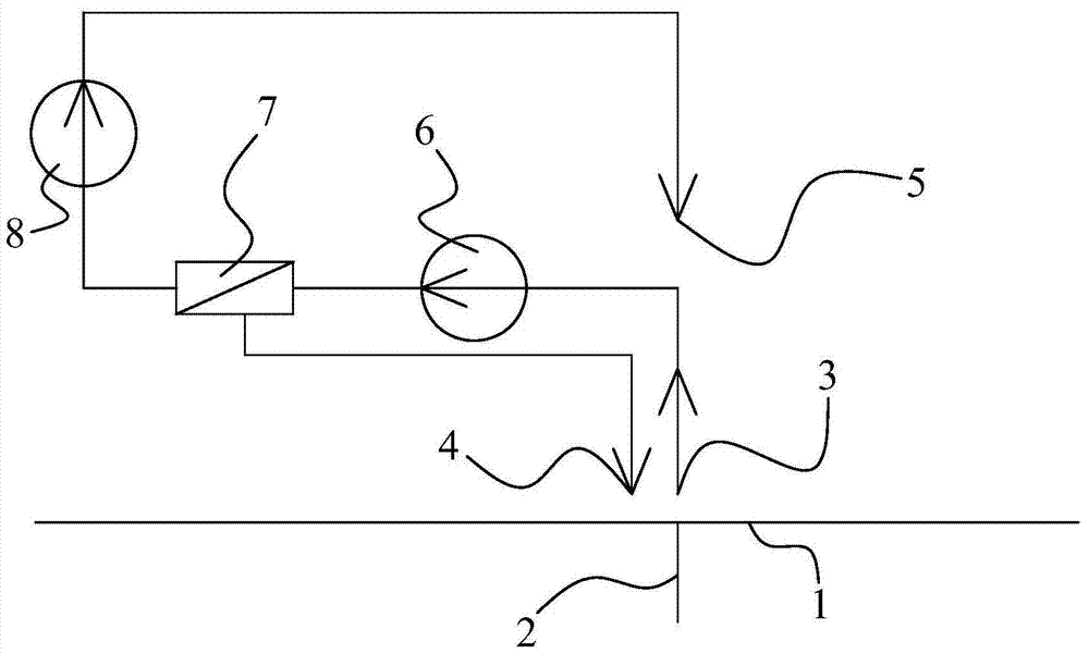
[0019] Embodiment 1, figure 1 A high-gravity reverse osmosis solution separation device and method are provided. The high-gravity reverse osmosis solution separation device comprises a rotating shaft 2, which is provided with a base 1; on the base 1, a high-pressure pump 8, a reverse osmosis device 7, a solution pump 6, pipeline A, pipeline B, and pipeline C (through the base 1 The high-pressure pump 8, the reverse osmosis device 7, the solution pump 6, the pipeline A, the pipeline B and the pipeline C) which can be stably arranged on the rotating shaft 2.

[0020] The liquid inlet of solution pump 6 is provided with a dilute solution inlet 3 through pipeline A; the liquid outlet of solution pump 6 is connected to the liquid inlet of reverse osmosis device 7; the water outlet of reverse osmosis device 7 is connected to the liquid inlet of high-pressure pump 8; the liquid outlet of high-pressure pump 8 is set through pipeline C There is a pure water outlet 5; the liquid outlet...

Embodiment 1

[0032] The calculation parameters of implementation example 1 are shown in Table 1 (for 1 kg of water). The design conditions are: the radius of gyration of the system is 0.5m, reverse osmosis is performed on seawater, the content of calcium ions in the feed seawater is 360ppm, the content of magnesium ions is 1176ppm, the content of sodium ions is 10065ppm, the content of potassium ions is 366ppm, and the content of sulfate ions is 2480ppm , the chloride ion content is 18152ppm, the temperature is 25°C, the seawater osmotic pressure is 2.4Mpa, the water production rate of the system is 25%, the osmotic pressure of the discharged concentrated seawater is 3.2Mpa, and the average driving pressure difference of the reverse osmosis process is 2.95Mpa, The system speed is 2004 rpm, the power consumption of the high-pressure pump and the solution pump are 6.88kJ / kg and 2.5kJ / kg respectively, and the exergy efficiency of the system (defined as the ratio of the minimum separation work ...


PUM


Abstract

The invention discloses a high-gravity reverse osmosis solution separation device; it comprises a rotating shaft (2), on which a high-pressure pump (8), a reverse osmosis device (7), and a solution pump (6) are arranged; the The liquid inlet of the solution pump (6) is provided with a dilute solution inlet (3) through the pipeline A; the liquid outlet of the solution pump (6) is connected to the liquid inlet of the reverse osmosis device (7); the water outlet of the reverse osmosis device (7) is connected to the high pressure The liquid inlet of the pump (8); the liquid outlet of the high-pressure pump (8) is provided with a pure water outlet (5) through a pipeline C; the liquid outlet of the reverse osmosis device (7) is provided with a concentrated solution outlet (4) through a pipeline B.

Description

technical field [0001] The invention relates to the technical field of power equipment, in particular to a high-gravity reverse osmosis solution separation device and method. Background technique [0002] In the fields of air conditioning, power, and chemical technology, the separation of water in solution is often involved. For example, in seawater desalination projects, water must be separated from seawater. This separation process can be completed by reverse osmosis. The principle is to use high pressure to increase The chemical potential of water in the solution allows it to transfer to the other side of the membrane through the permeable membrane, thereby separating the solution. [0003] In reverse osmosis, the dilute solution is generally pressurized to a high pressure of Mpa level. After the water in the dilute solution permeates out through the osmotic membrane, the remaining concentrated solution still has a large liquid pressure energy, which can be recovered by a...

Claims


Application Information

Patent Timeline
Patent Type & Authority Patents(China)
IPC IPC(8): B01D61/08C02F103/04C02F103/08
Inventor 王厉
Owner ZHEJIANG SCI-TECH UNIV
Features
  • R&D
  • Intellectual Property
  • Life Sciences
  • Materials
  • Tech Scout
  • Unparalleled Data Quality
  • Higher Quality Content
  • 60% Fewer Hallucinations
Learn More